
Big-Bore Evo Motor Build
Remember the days when the ol’ Evolution motor started right up, didn’t leak all over the place, and didn’t make your hands numb while riding? No? We don’t either, so when it came time to refresh our 1997 Dyna motor, we chose a Revolution Performance bottom end consisting of a reconditioned flywheel assembly, balanced, trued, and installed topped off with its 85ci Nikasil cylinder and piston kit. The end result is a bolt-on Evo big-bore kit that provides the extra power that any of you Evolution-engine owners would welcome.
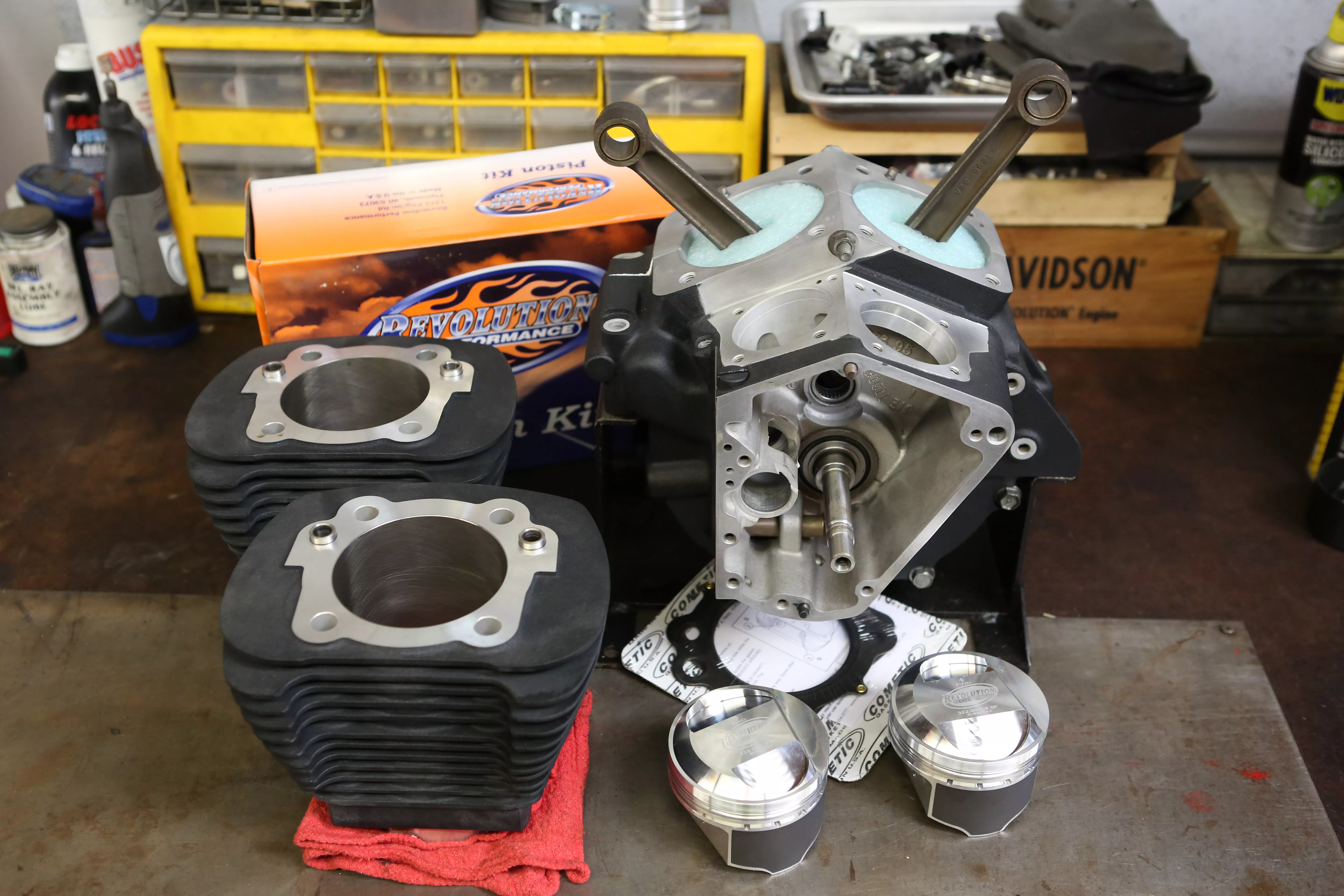
Our 1997 bottom end returns to us from Revolution Performance very well packed for shipping. The engine case and flywheel have been rebuilt and reconditioned and assembled for install. Also included is the Revolution Performance 85-inch bolt on Nikasil cylinder and piston kit as well as its stage 4 heads.
Words: Chip Katstelnik Photos: Mikey Van Senus
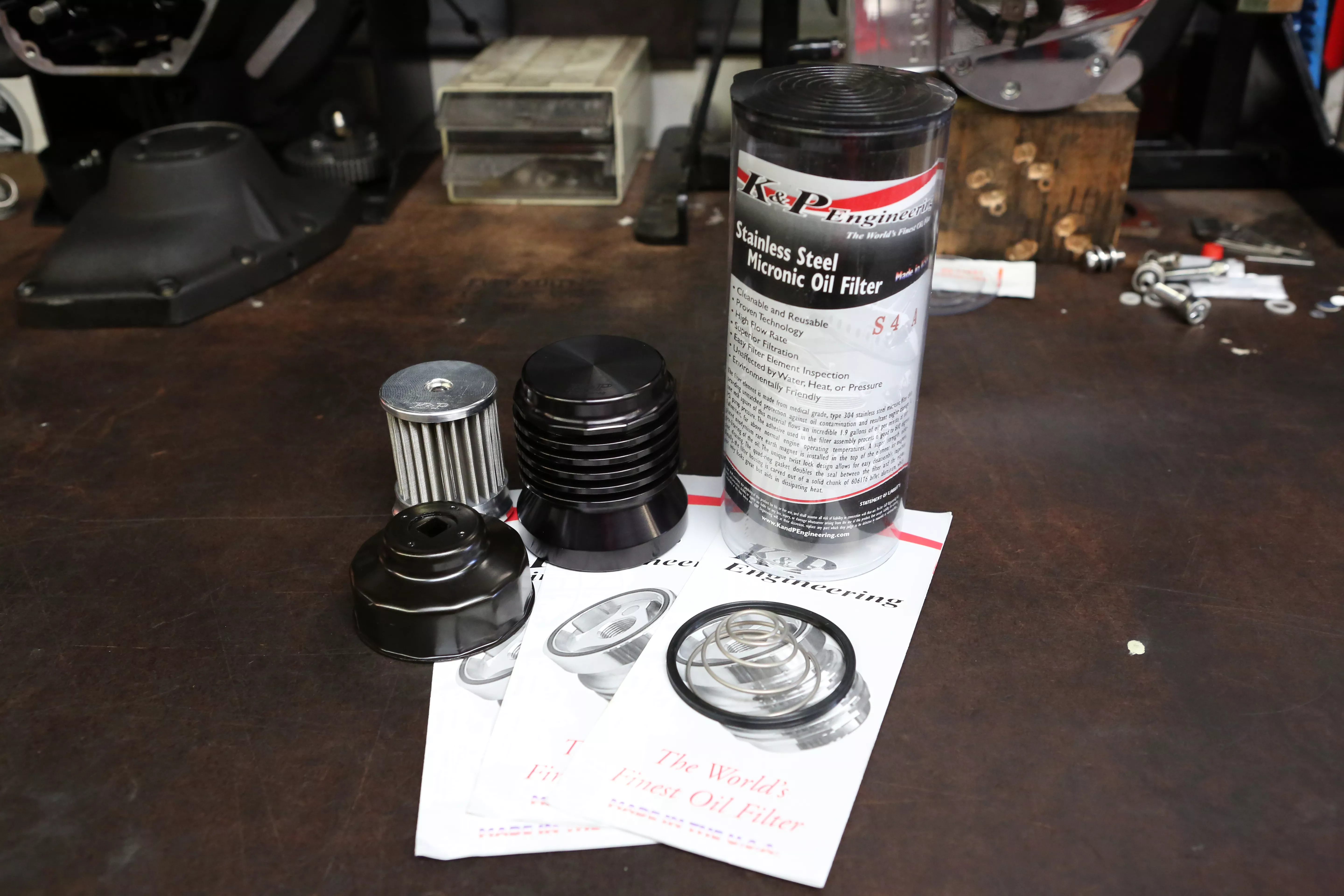
We will be using the K&P stainless steel micronic oil filter, which has a cleanable, reusable filter element.
Words: Chip Katstelnik Photos: Mikey Van Senus
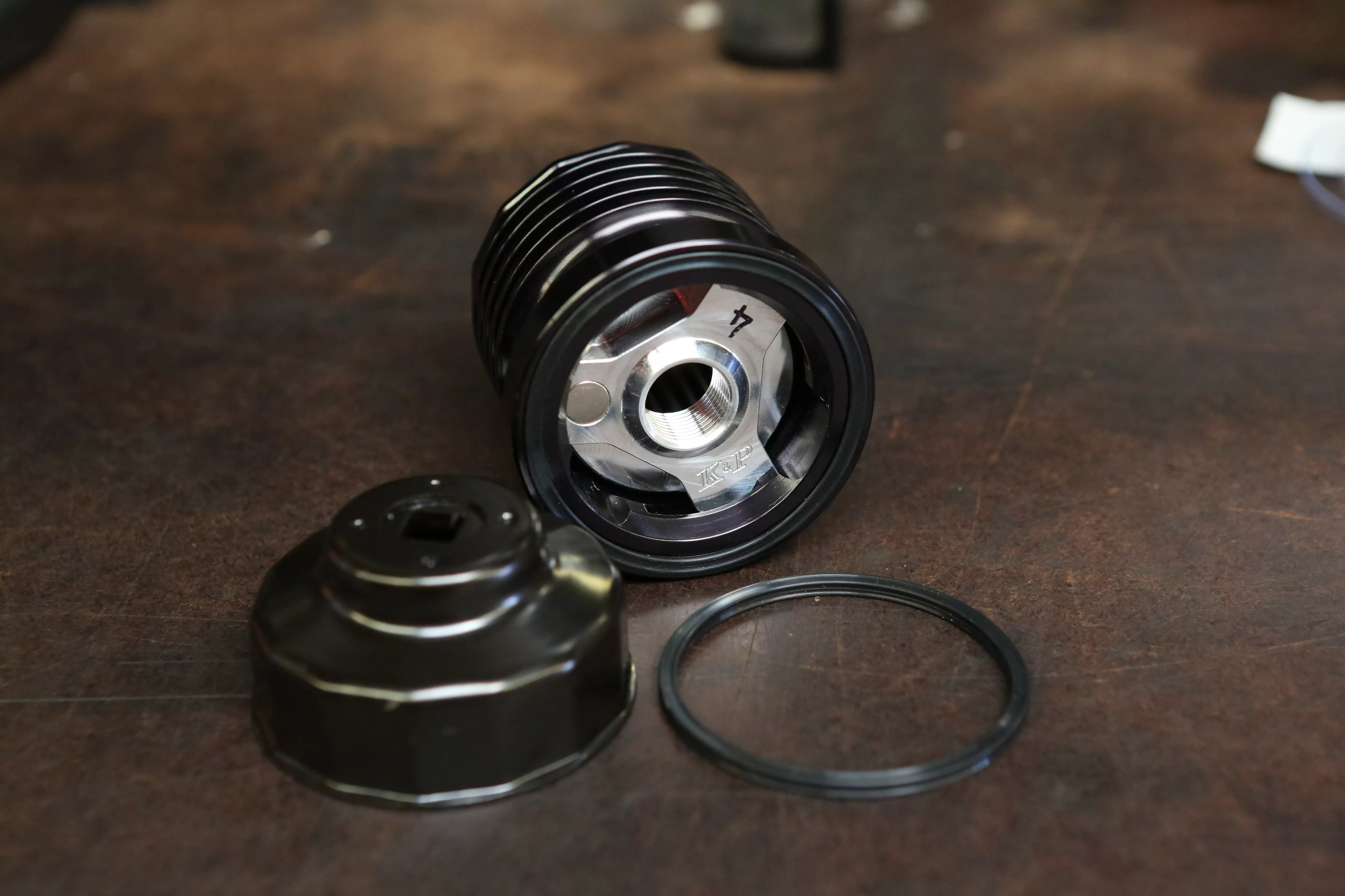
We will be using the K&P stainless steel micronic oil filter, which has a cleanable, reusable filter element.
Words: Chip Katstelnik Photos: Mikey Van Senus
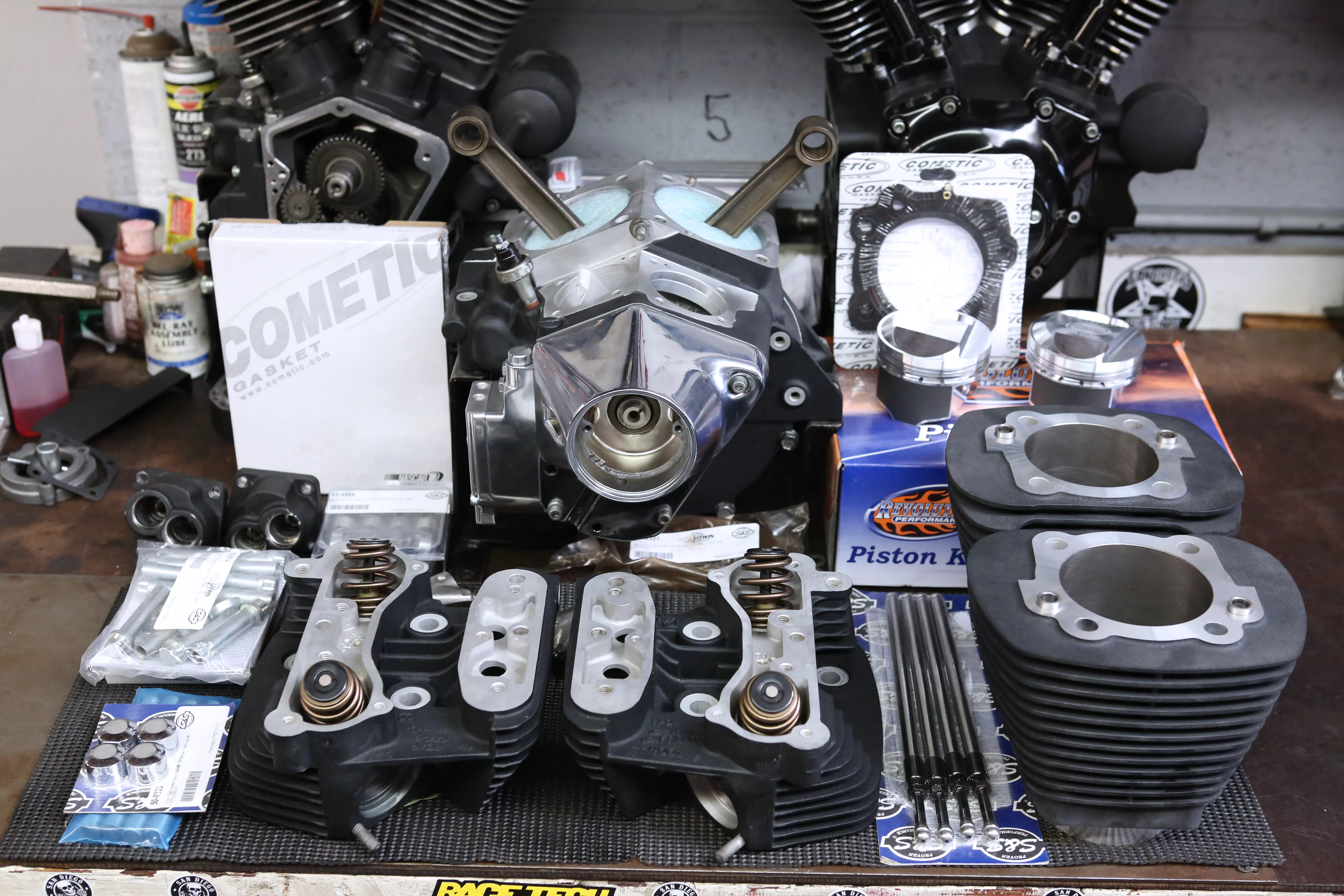
Here’s our pile of new parts for the rebuild from Revolution Performance, Cometic, and S&S. All you need to go fast faster.
Words: Chip Kastelnik Photos: Mikey Van Senus
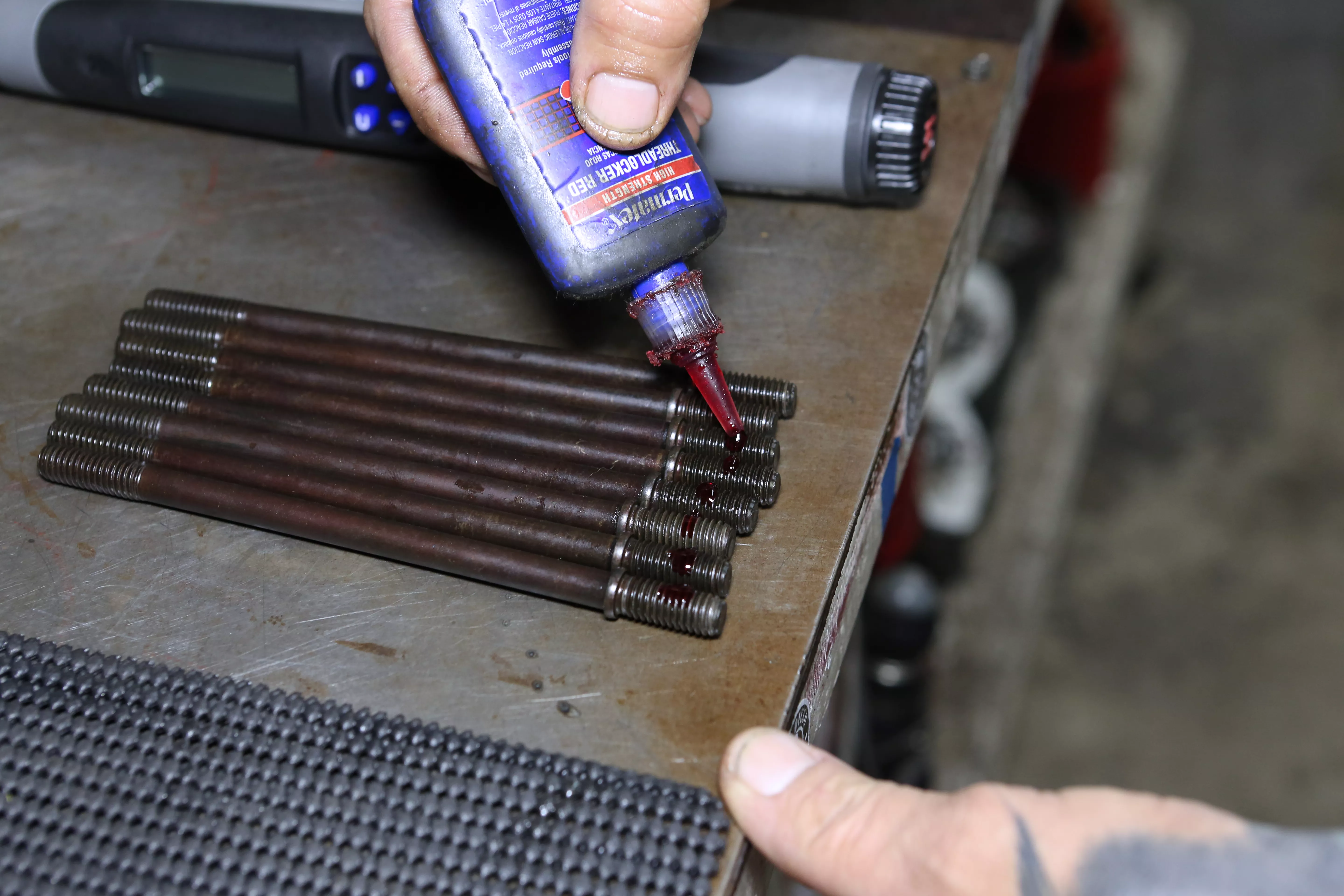
To begin, we installed a few drops of red Loctite onto the cylinder studs prior to installing.
Words: Chip Kastelnik Photos: Mikey Van Senus
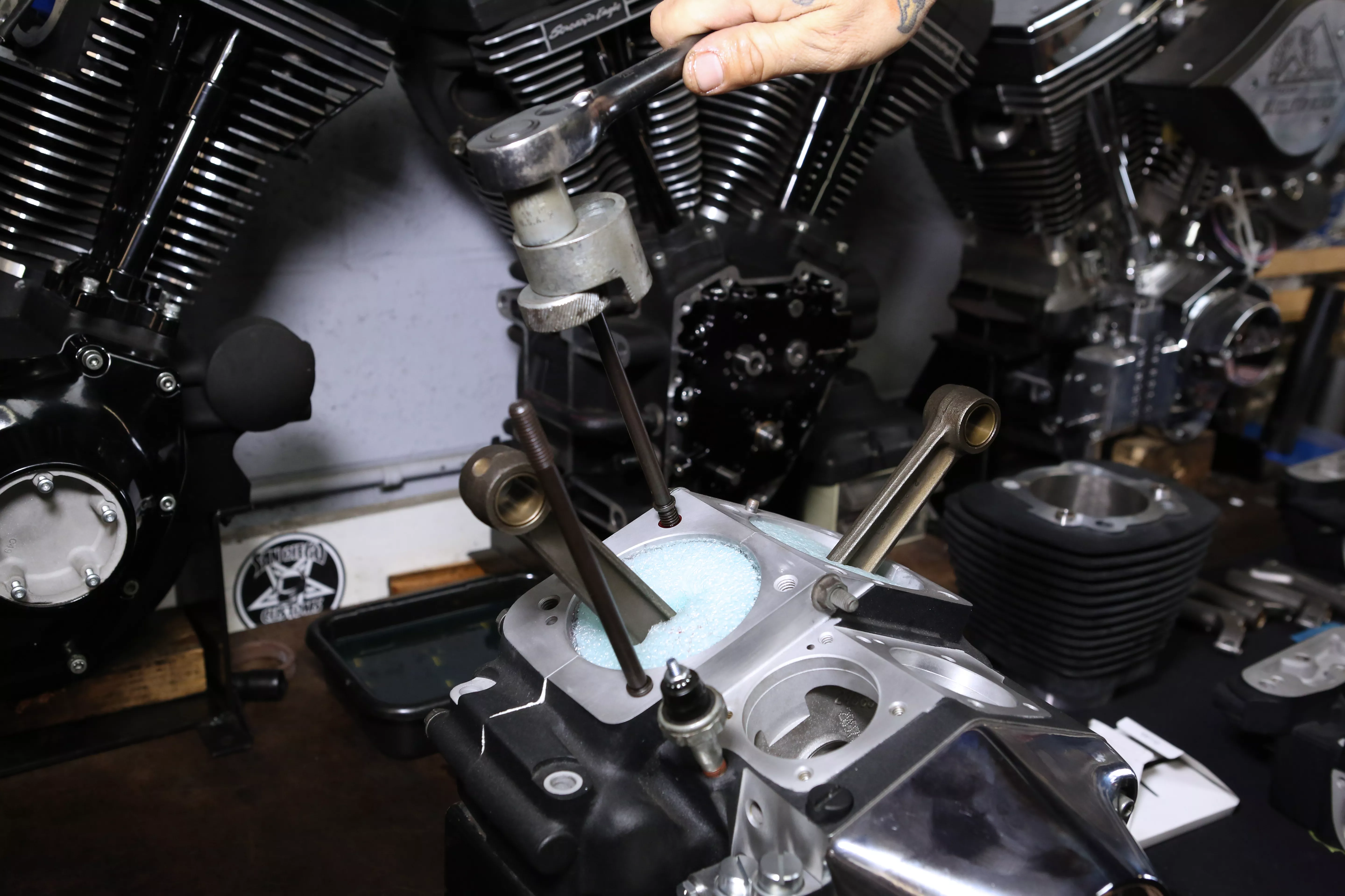
Using a stud installer tool, we were able to install all the studs into their locations without marring the threads.
Words: Chip Kastelnik Photos: Mikey Van Senus
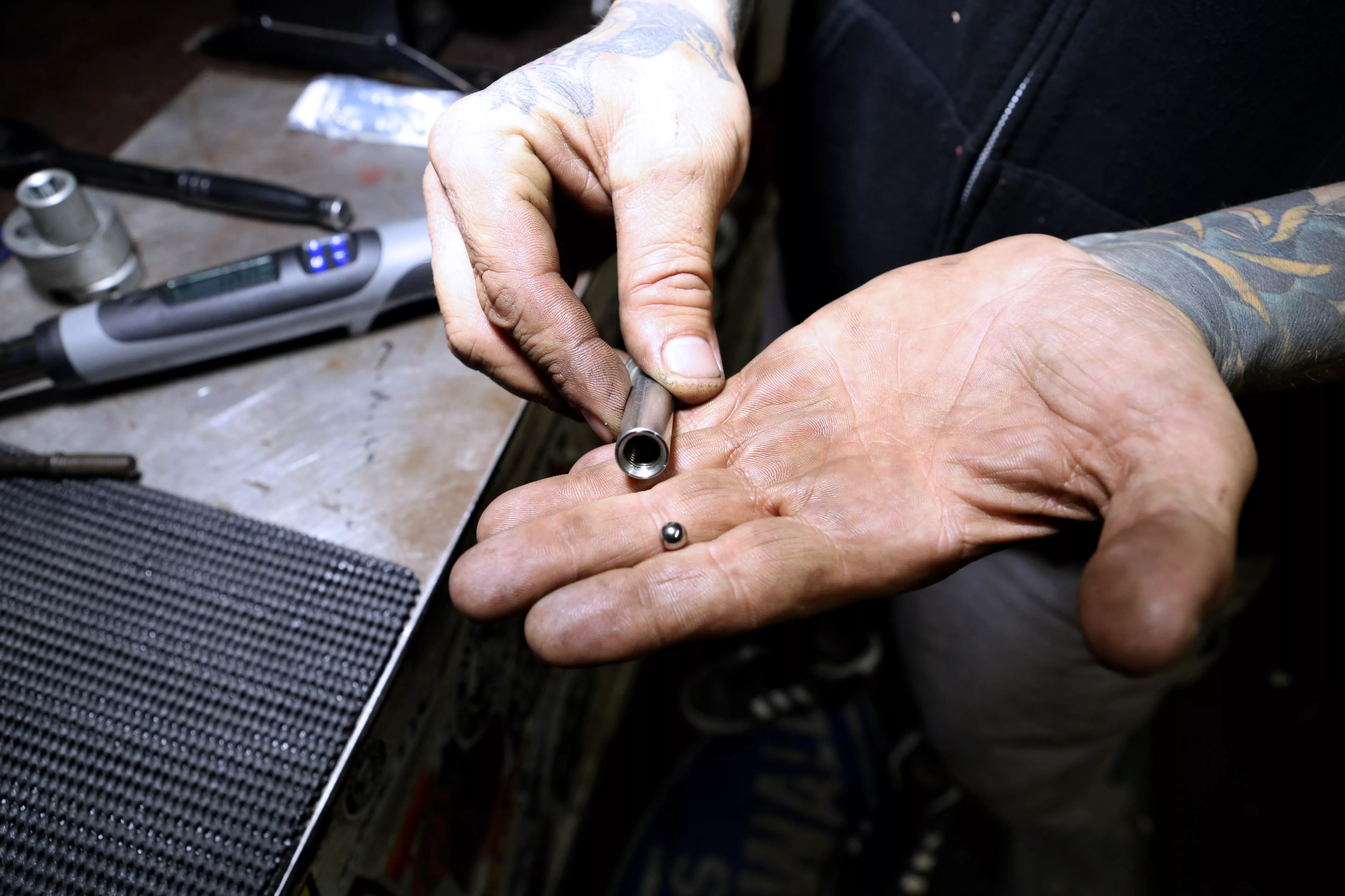
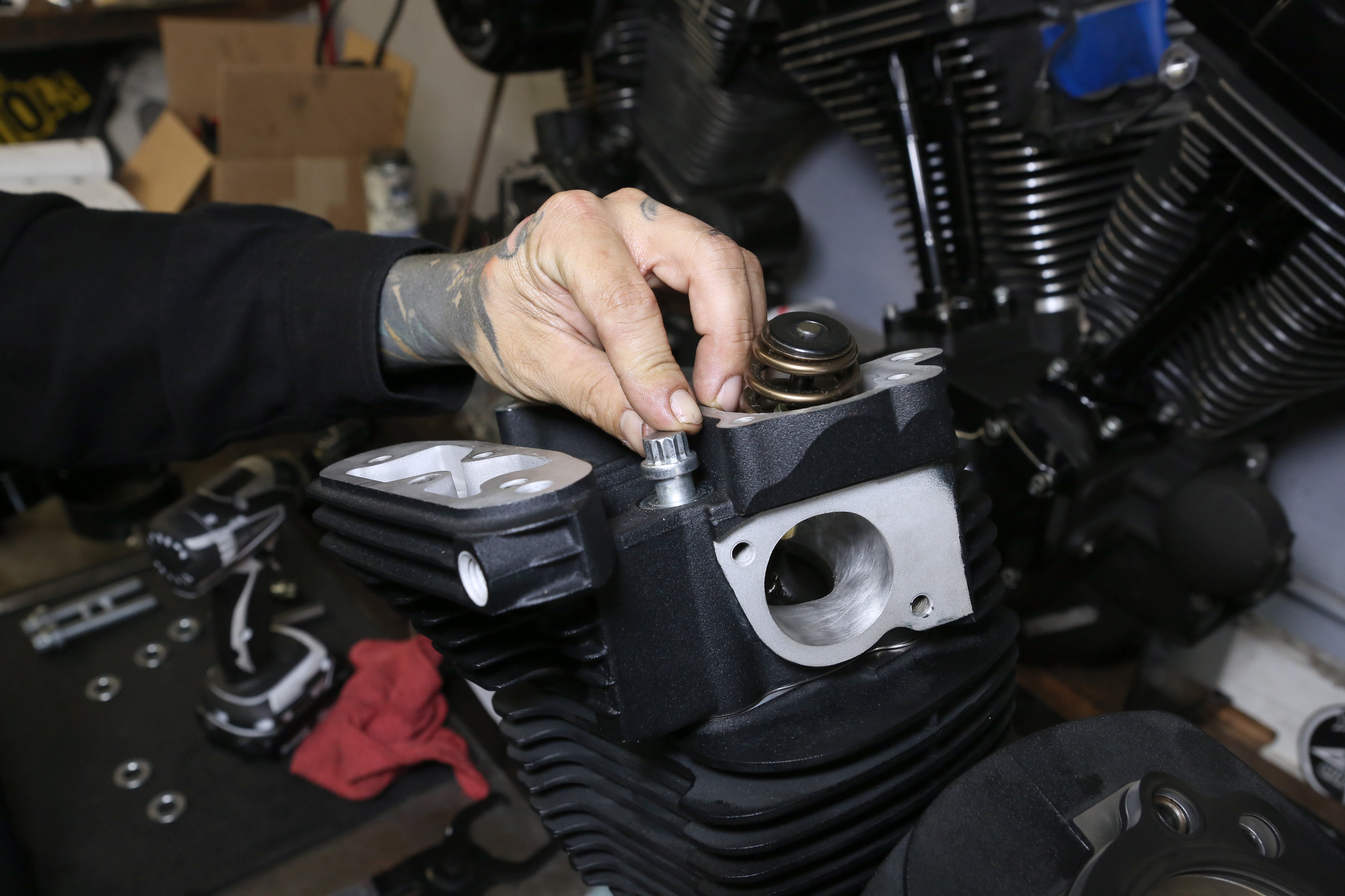
To torque the cylinder studs, we installed a small ball bearing into a head bolt. This enables a proper torque. The ball bearing will allow you to remove the head bolt without removing the stud.
Words: Chip Kastelnik Photos: Mikey Van Senus
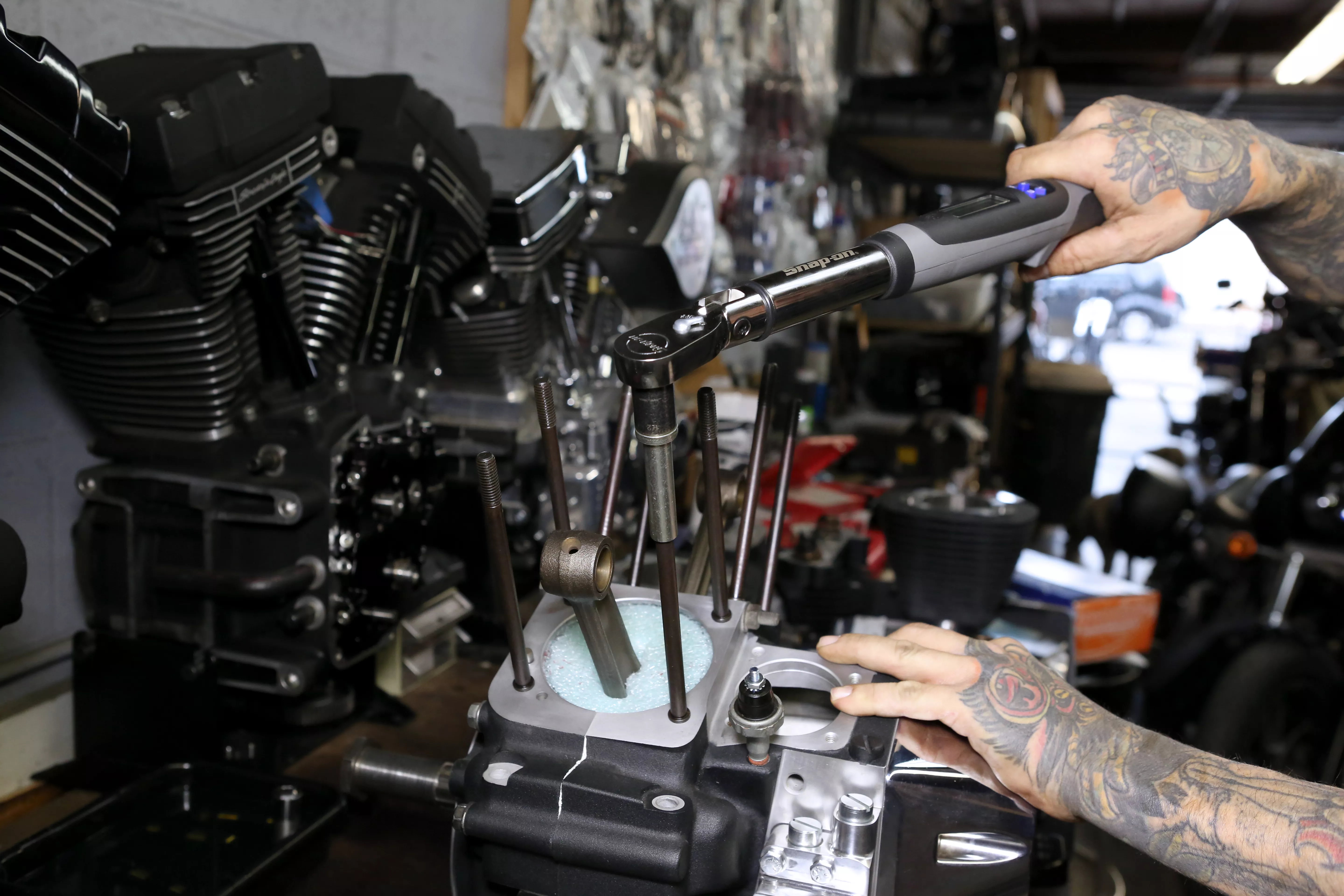
With the ball in the head bolt, we torqued the head bolts to the manufacturer’s recommended specs.
Words: Chip Kastelnik Photos: Mikey Van Senus
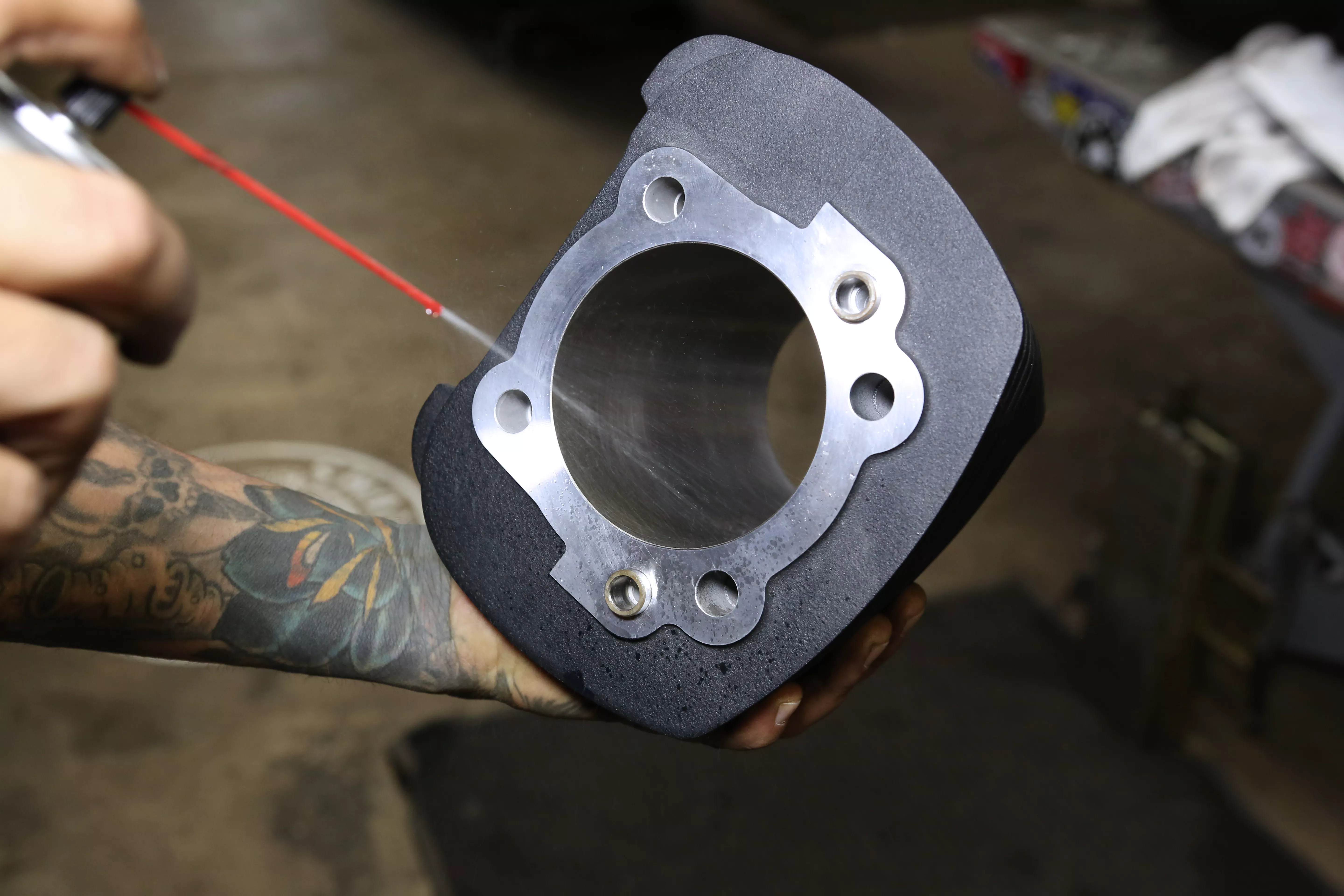
Prior to installing the top end, be sure to first clean the cylinders with soapy water to be certain there is no debris that could cause damage. We re-cleaned the cylinders with brake cleaner after washing.
Words: Chip Kastelnik Photos: Mikey Van Senus
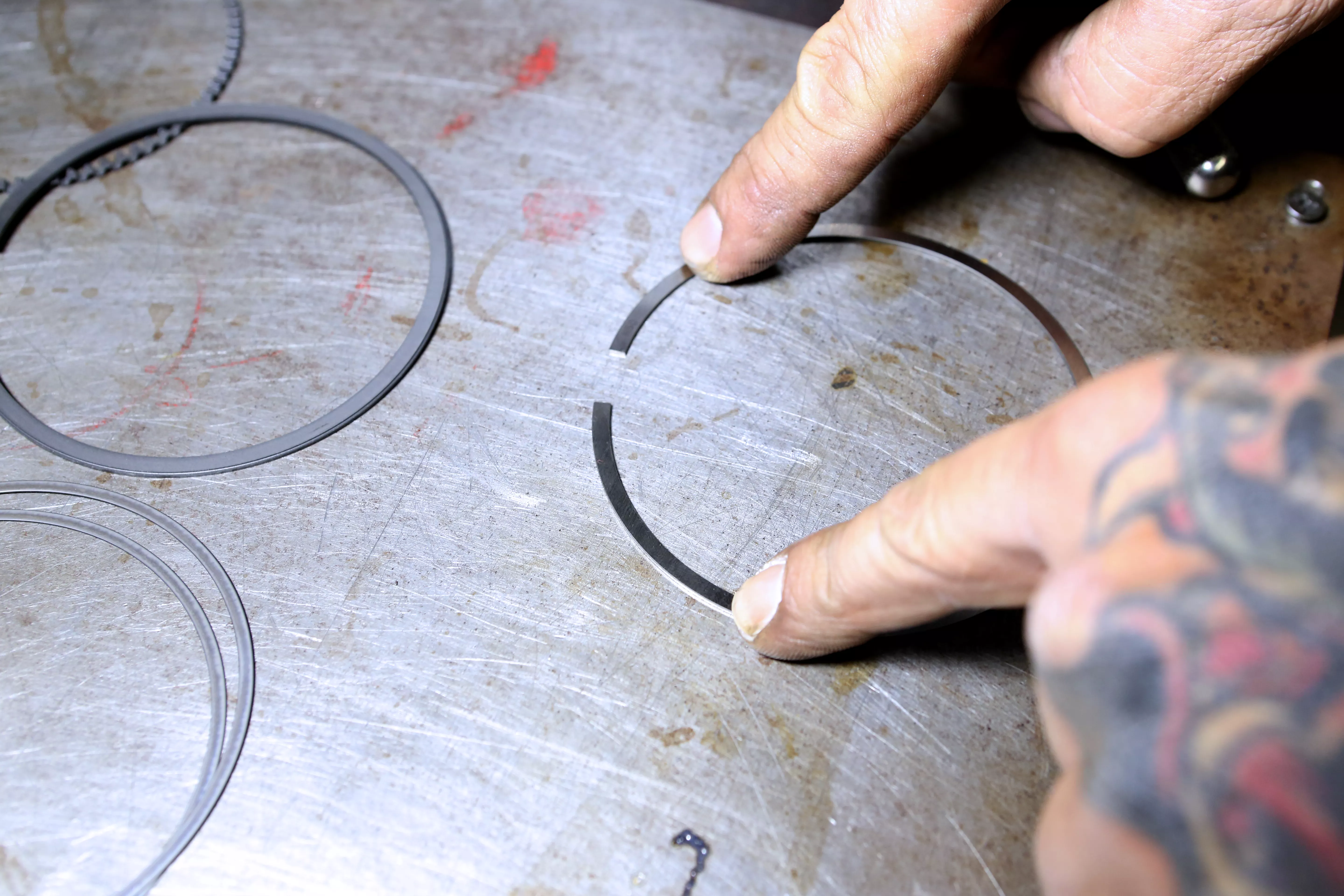
Then we layed out the piston rings and checked for damage or bending in any ring surfaces.
Words: Chip Kastelnik Photos: Mikey Van Senus
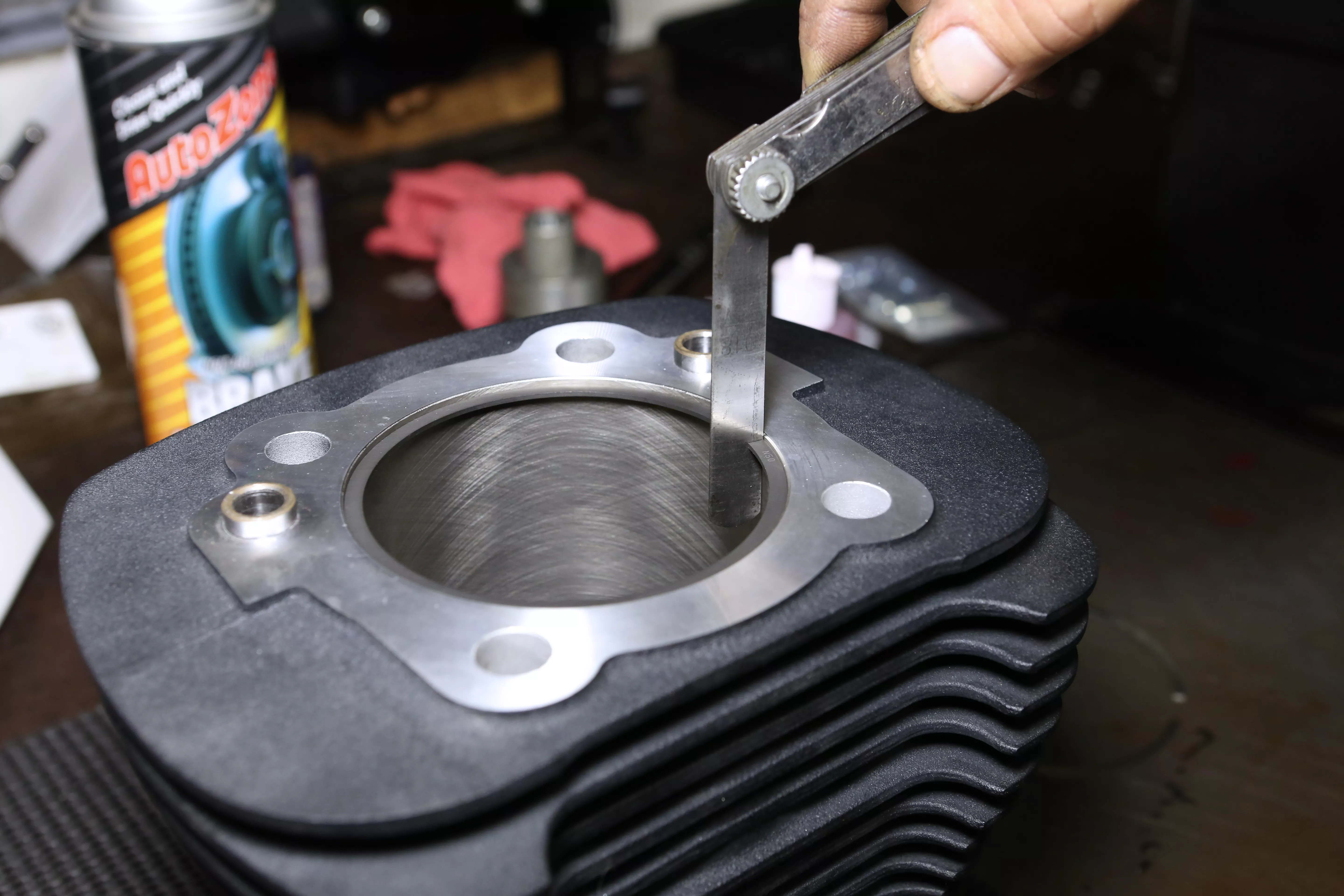
Next we placed the piston ring into the cylinder and level with the piston. We took a feeler gauge to measure the gap of the piston ring then repeated the process on all rings. Using a piston ring cutting tool, we cut the rings to the appropriate sizes.
Words: Chip Kastelnik Photos: Mikey Van Senus
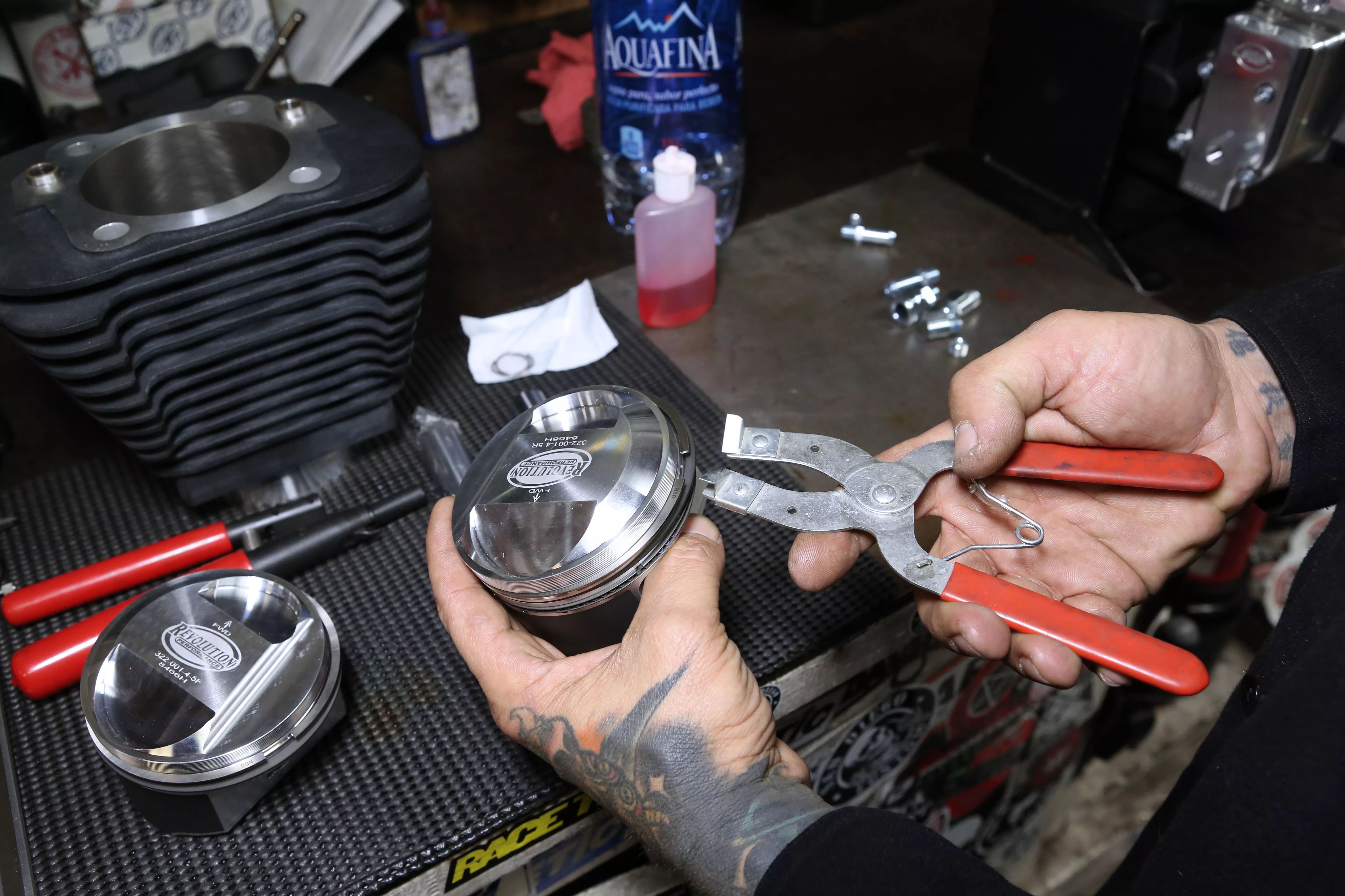
After the rings were sized, we installed the piston using a piston ring spreader tool. This tool ensures the piston rings will not mar or scrape the pistons sides when installing.
Words: Chip Kastelnik Photos: Mikey Van Senus
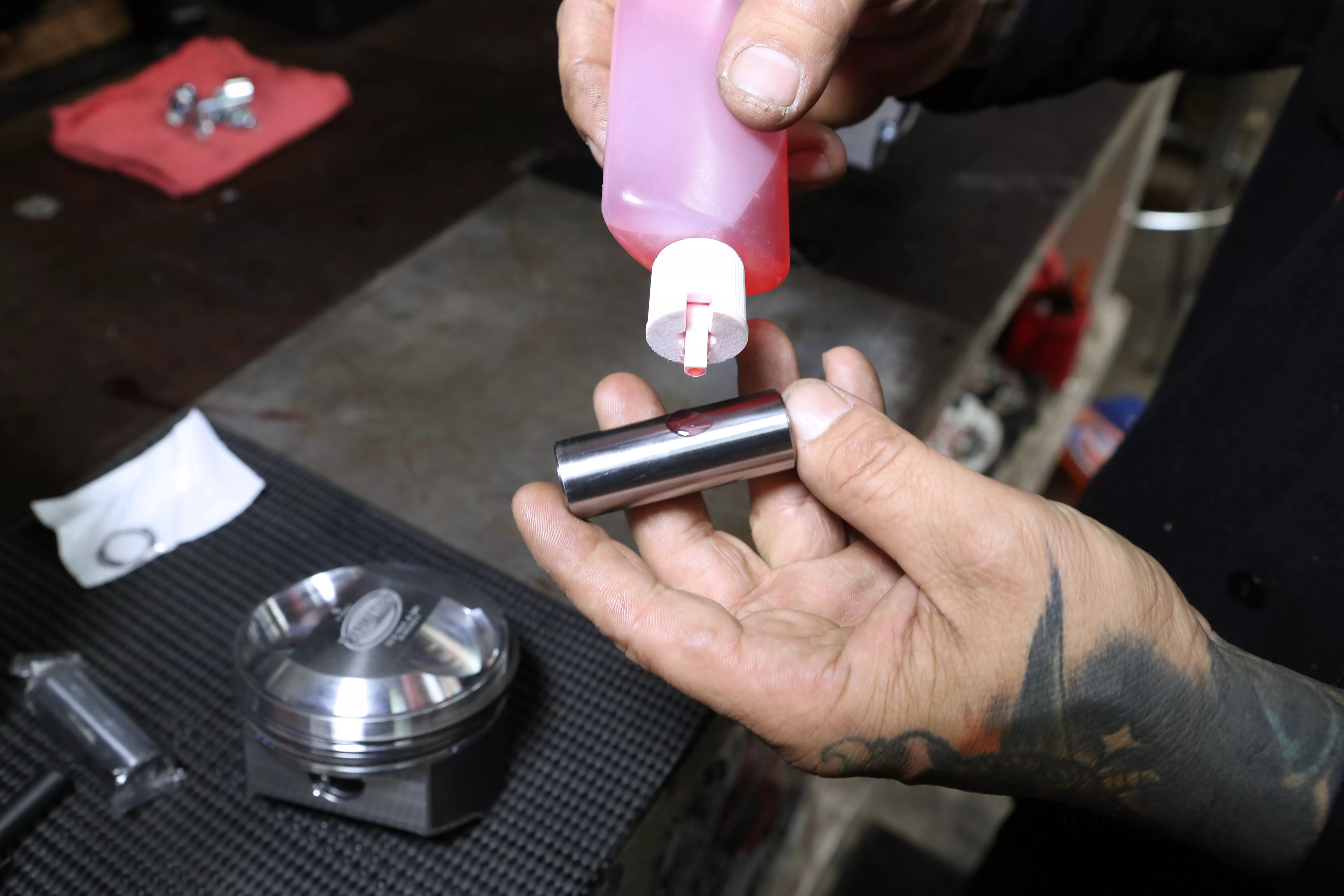
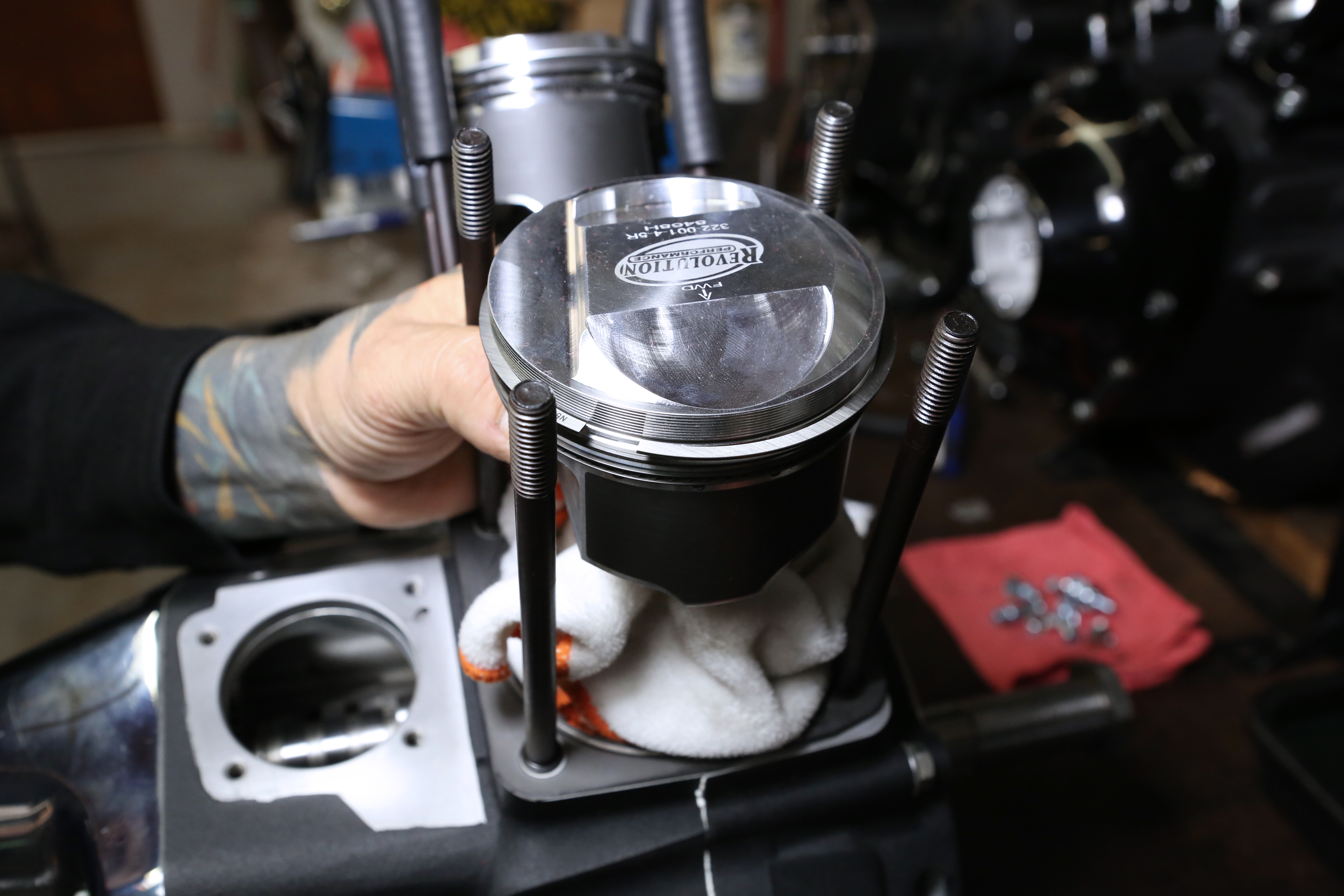
Using the Revolution Performance supplied assembly lubricant, we coated the wrist pin prior to installing the pistons onto the rods.
Words: Chip Kastelnik Photos: Mikey Van Senus
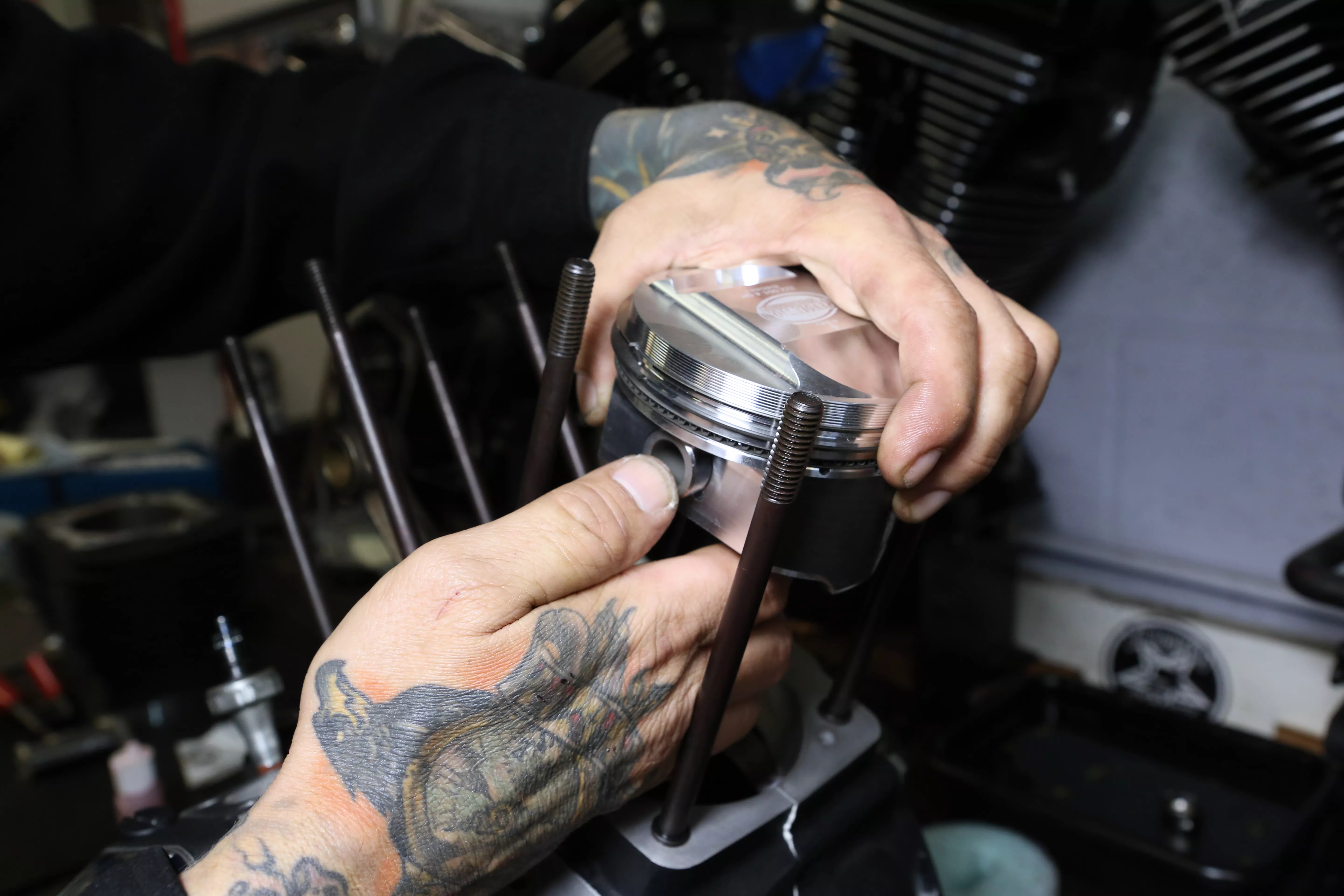
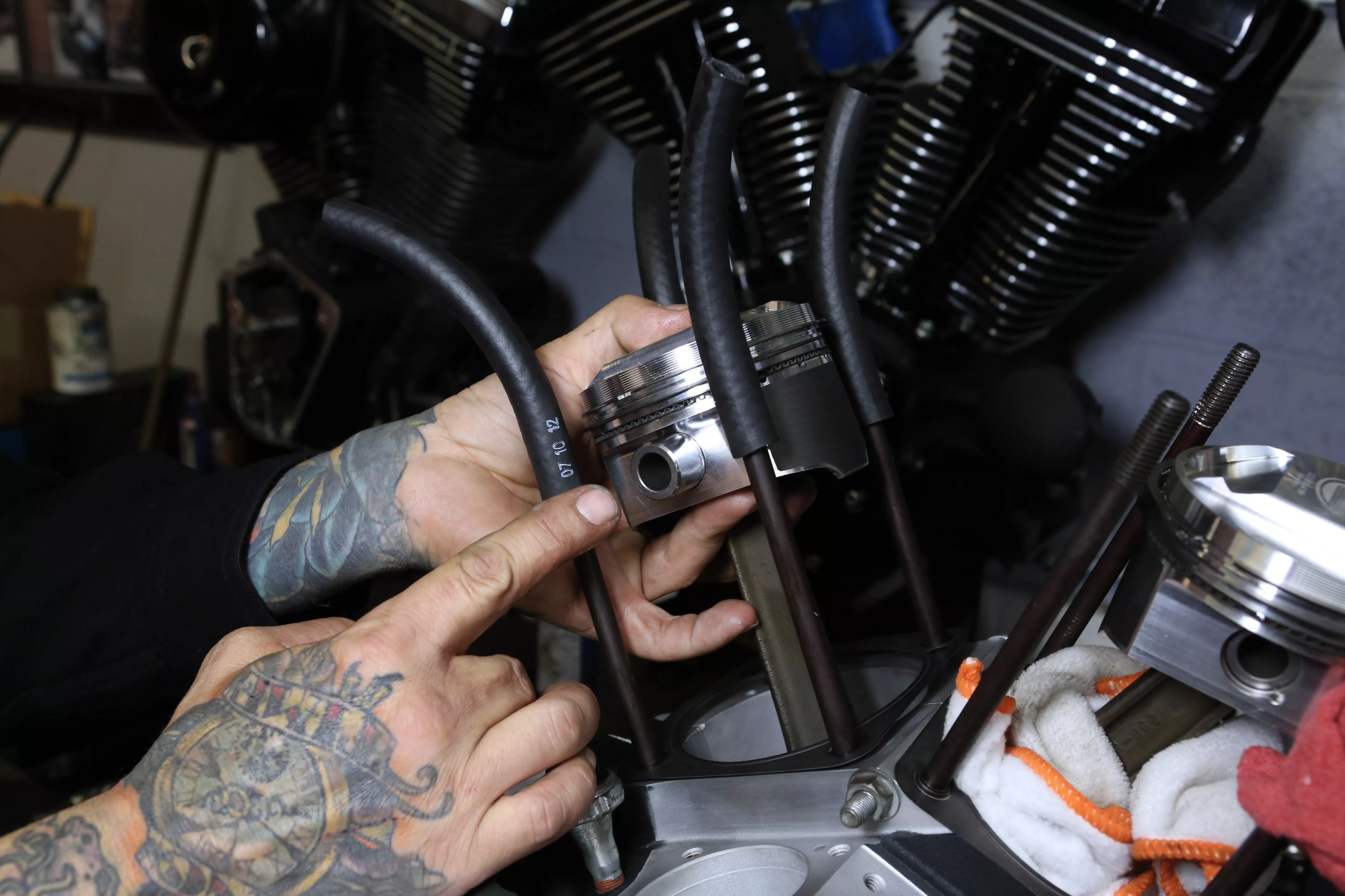
Making sure to install the pistons in the correct direction, we slid the wrist pin through the piston and connecting rod.
Words: Chip Kastelnik Photos: Mikey Van Senus
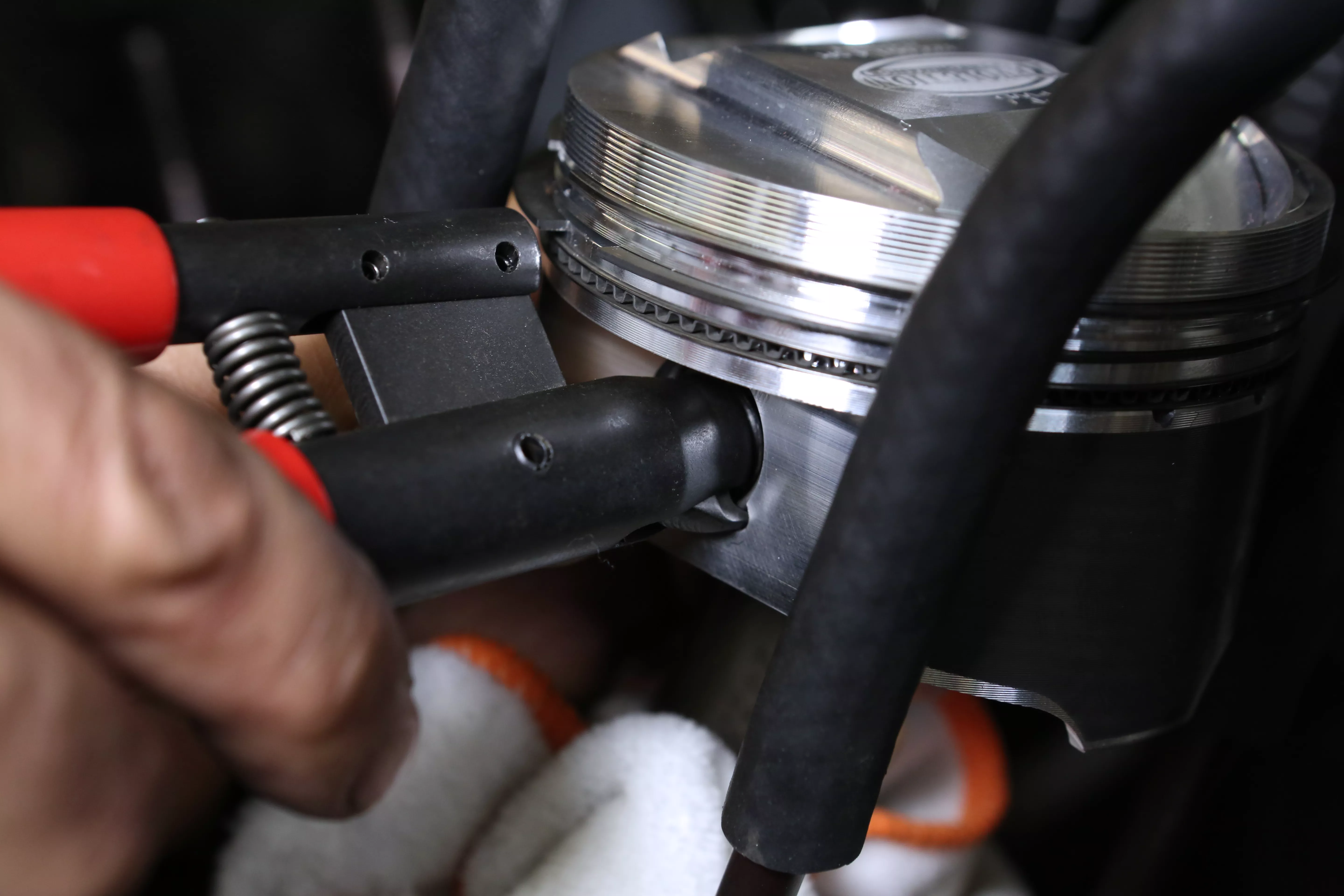
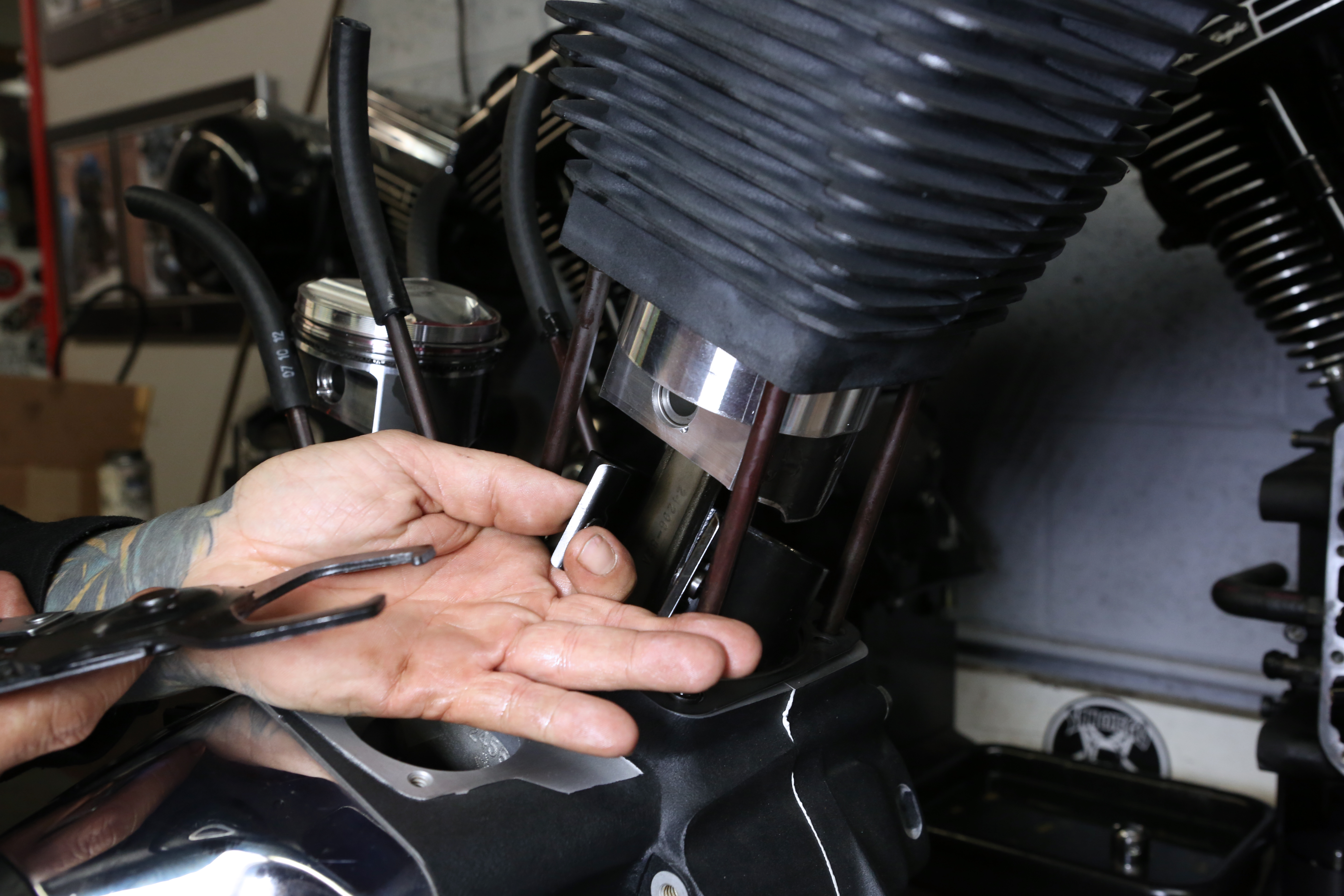
Using the correct tool, we installed the wrist pin retaining clip into the piston groove.
Words: Chip Kastelnik Photos: Mikey Van Senus
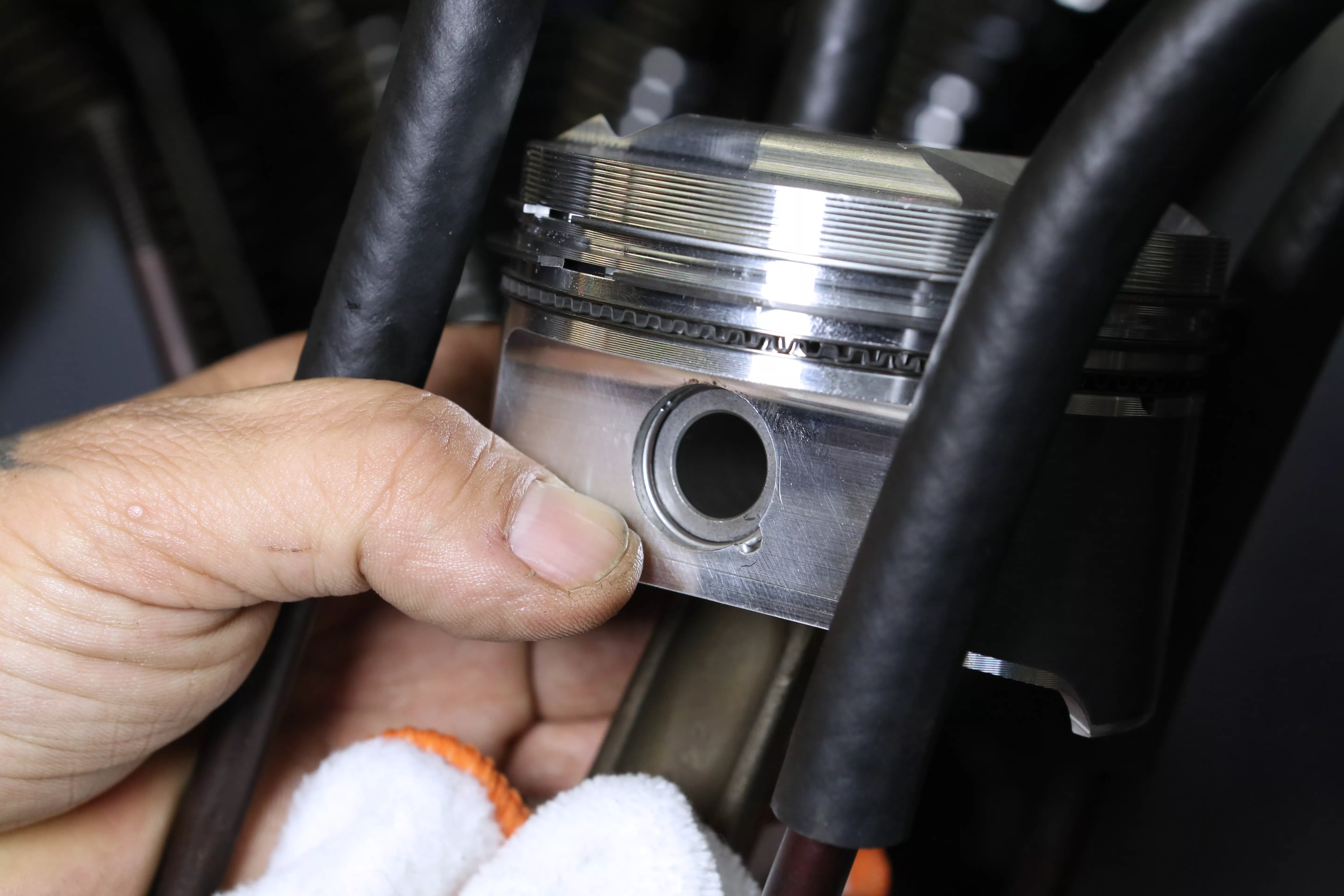
Here you can see the wrist pin clip is secure in the appropriate groove.
Words: Chip Kastelnik Photos: Mikey Van Senus
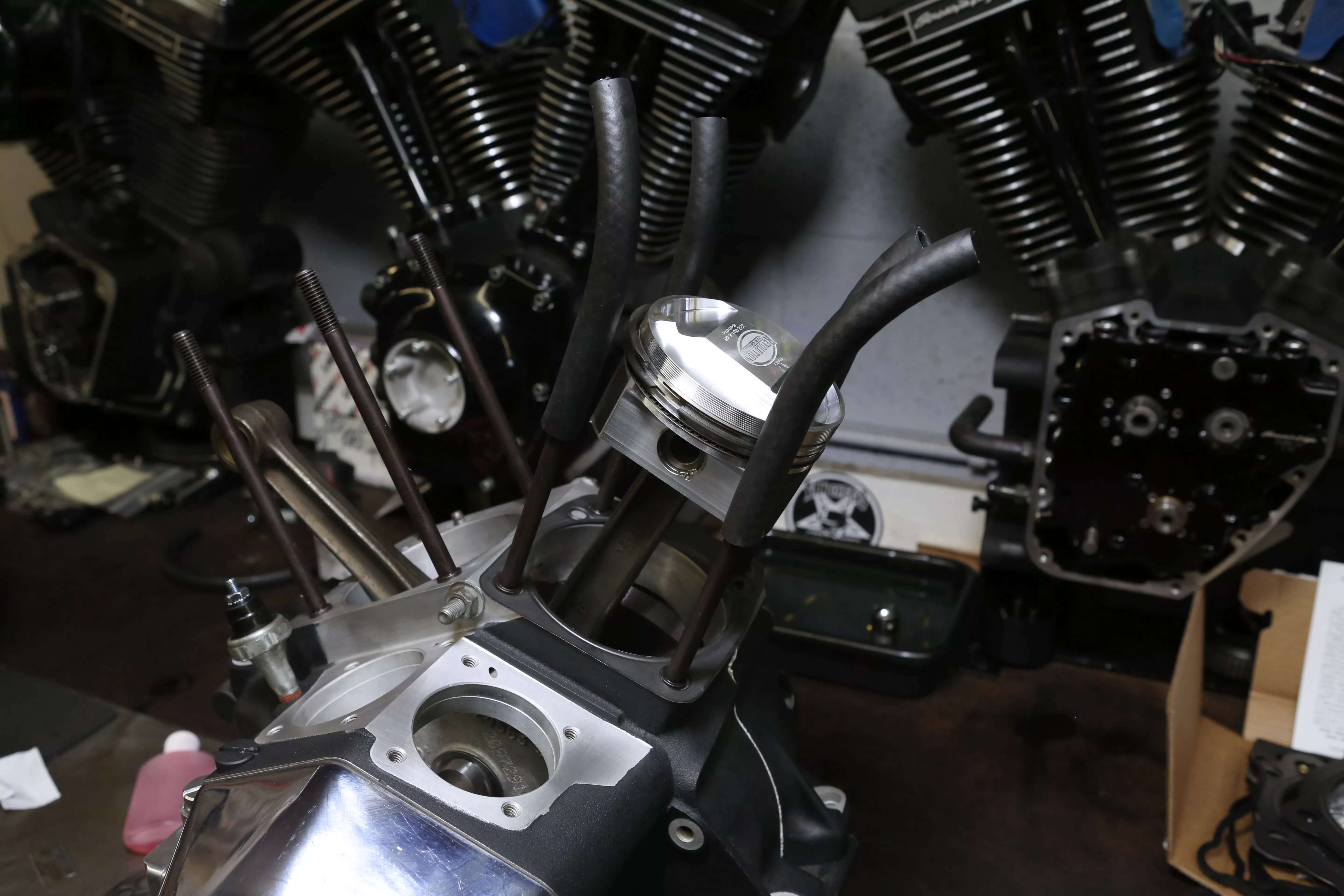
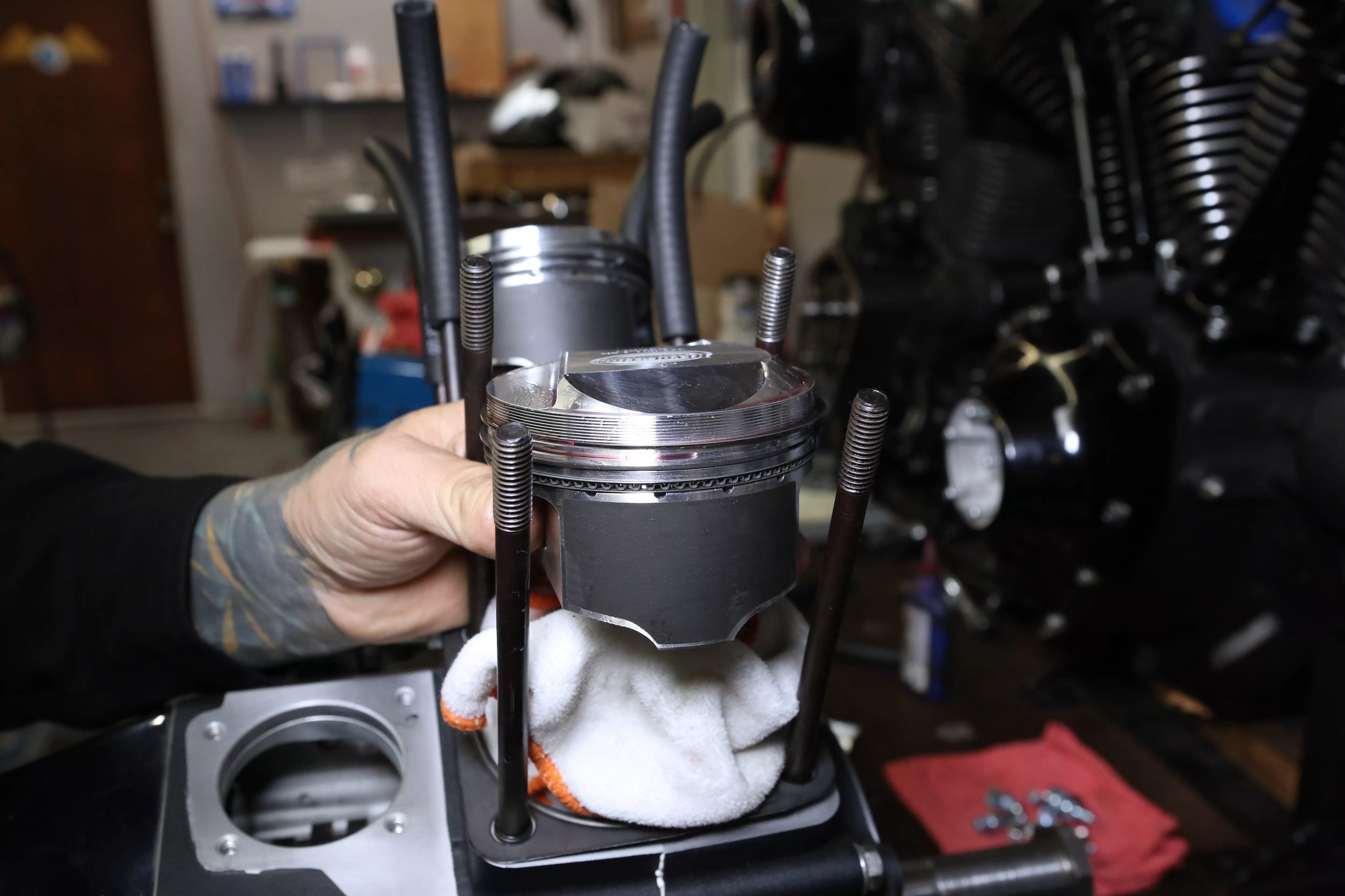
Pictured here is the front piston, rings, base gasket, and wrist pin clip installed.
Words: Chip Kastelnik Photos: Mikey Van Senus
Then we installed the rear base gasket and repeated the same process as doing the front cylinder.
Words: Chip Kastelnik Photos: Mikey Van Senus
Make sure to install the base gasket correctly.
Words: Chip Kastelnik Photos: Mikey Van Senus
We installed the rear piston, wrist pin, and retaining clip.
Words: Chip Kastelnik Photos: Mikey Van Senus
Verify the piston rings are in the correct locations and “X” pattern is the usual standard.
Words: Chip Kastelnik Photos: Mikey Van Senus
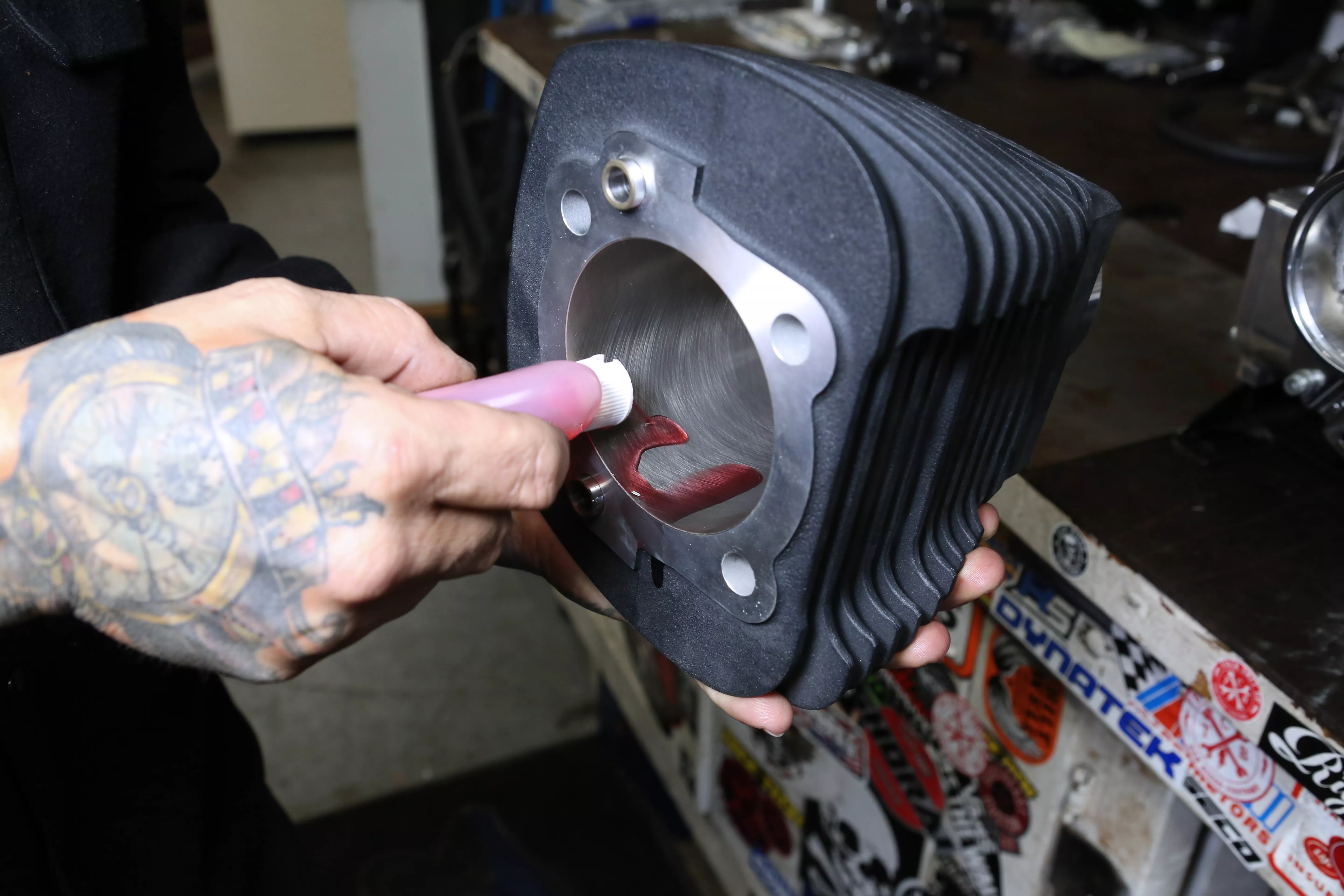
We applied a healthy amount of assembly lubricant in the cylinder and on the piston and rings.
Words: Chip Kastelnik Photos: Mikey Van Senus
Lube is your friend; it prevents scratches, galling, and metal-to-metal contact on startup.
Words: Chip Kastelnik Photos: Mikey Van Senus
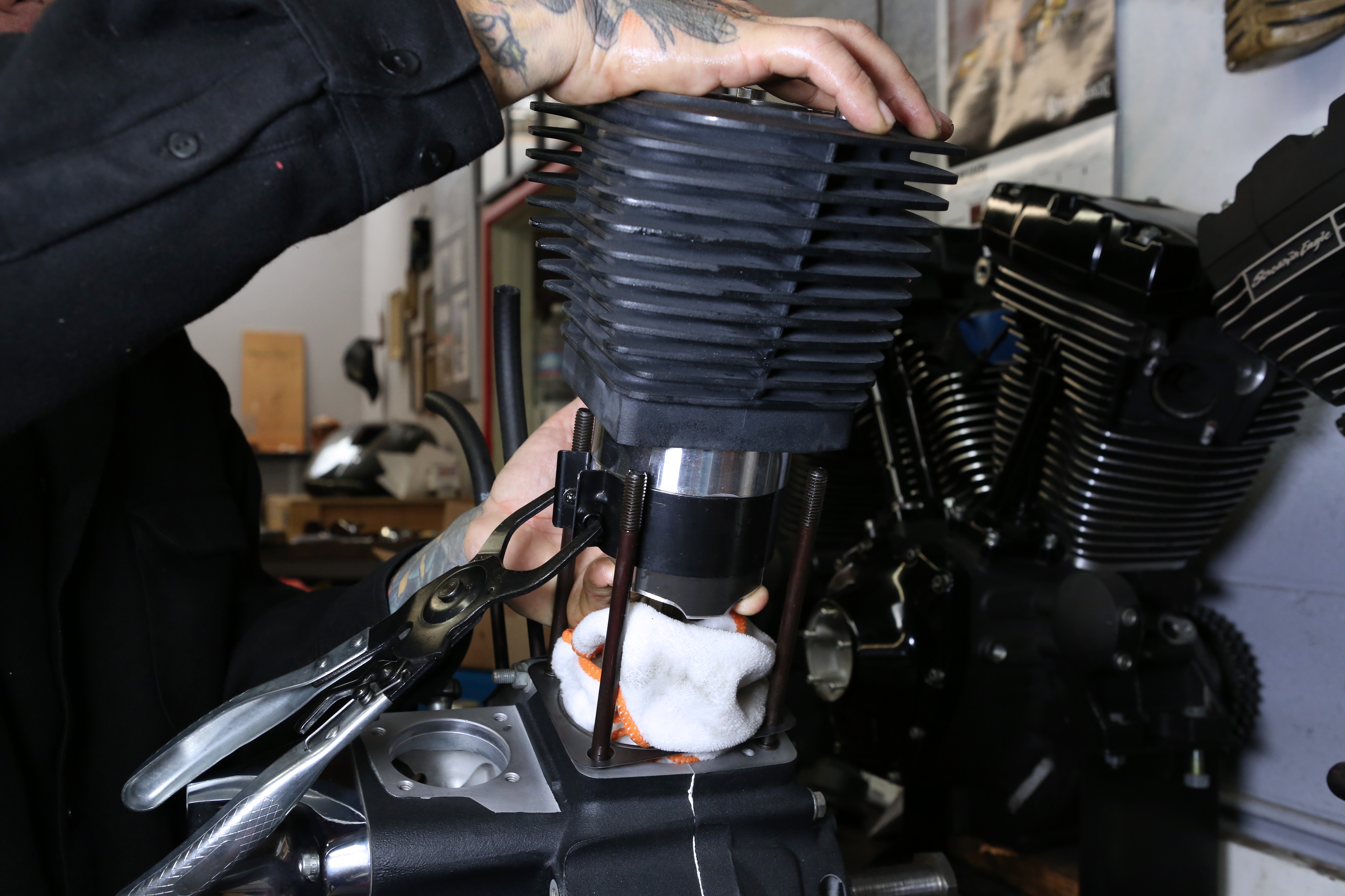
Using a piston ring compression tool, we squeezed the rings so the cylinder slipped over them. Be sure to remove any rags or tools before pushing cylinder on to engine case.
Words: Chip Kastelnik Photos: Mikey Van Senus
We removed the ring compression tool carefully, repeating the procedure on the rear cylinder.
Words: Chip Kastelnik Photos: Mikey Van Senus
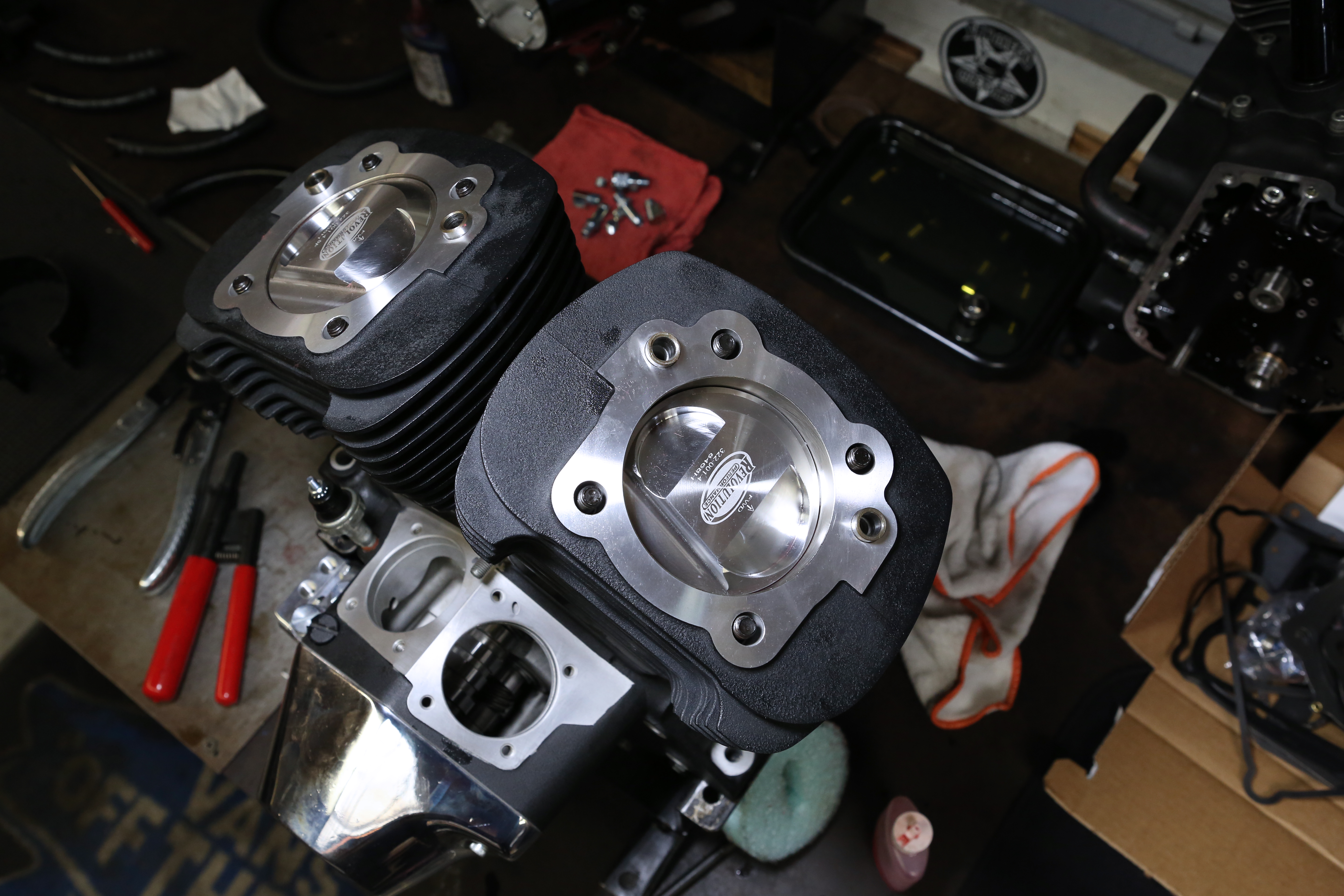
Pictured here is the front and rear cylinder installed. Note that the directional arrows point to the correct piston direction.
Words: Chip Kastelnik Photos: Mikey Van Senus
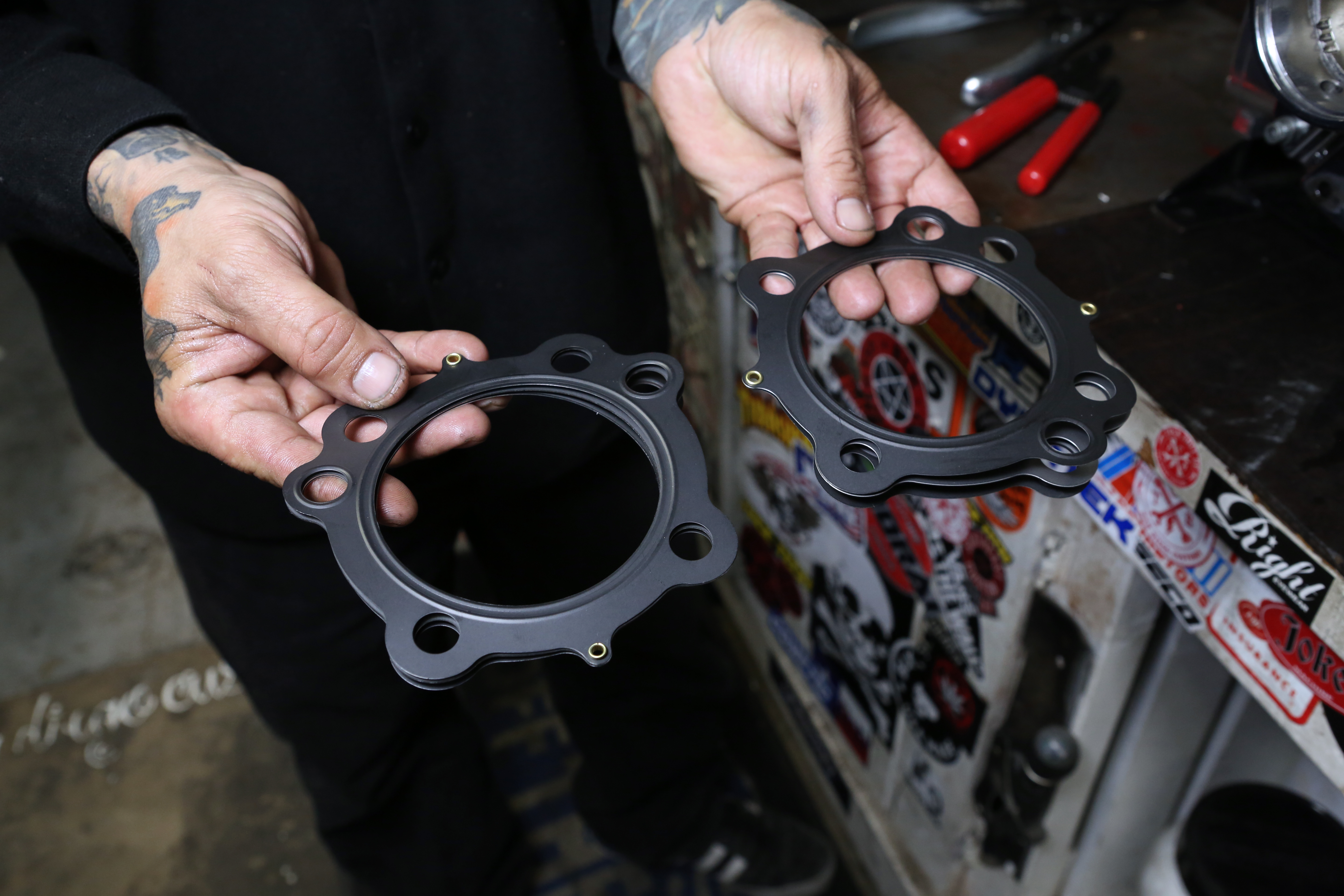
Next we installed out .030 Cometic MLS head gaskets.
Words: Chip Kastelnik Photos: Mikey Van Senus
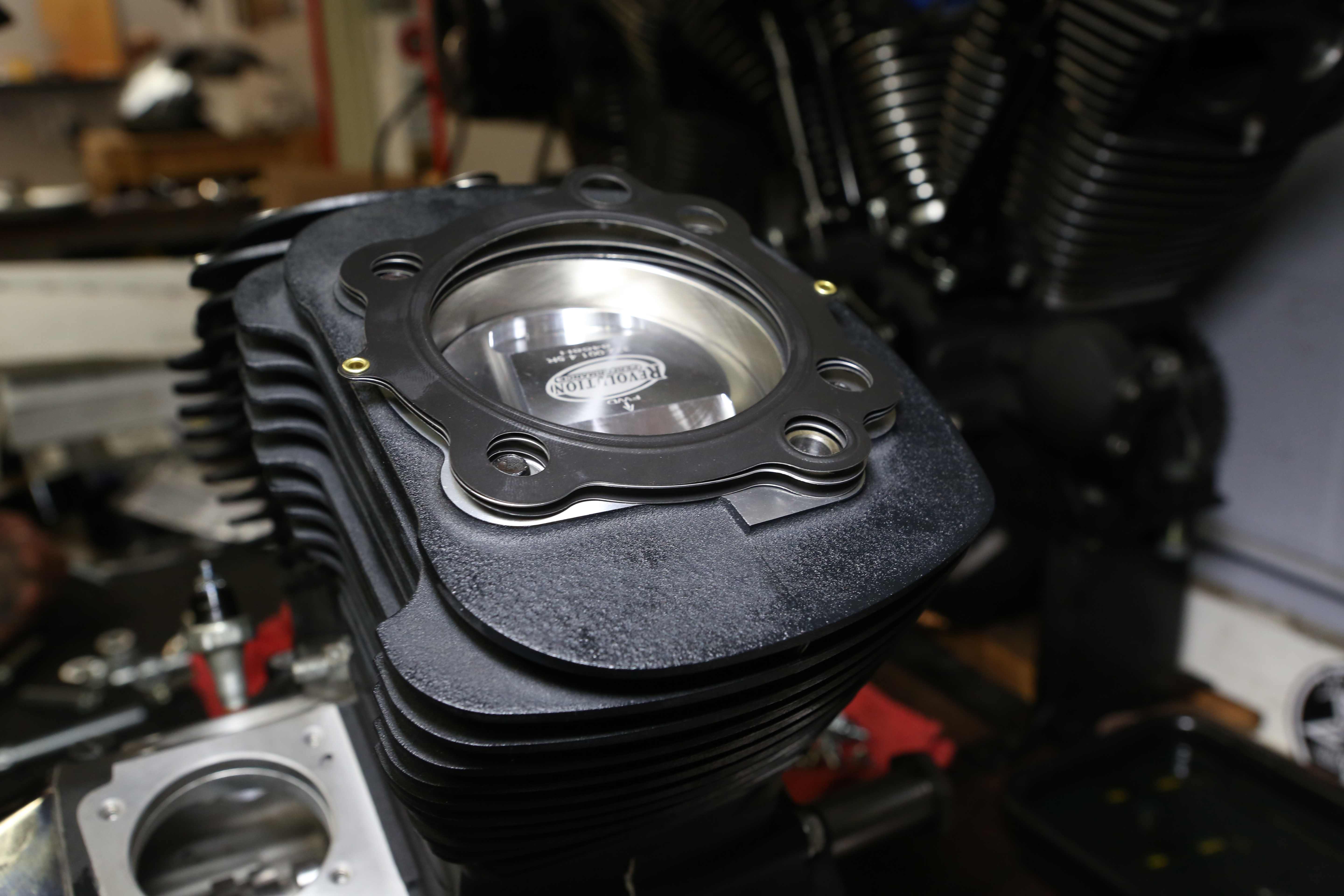
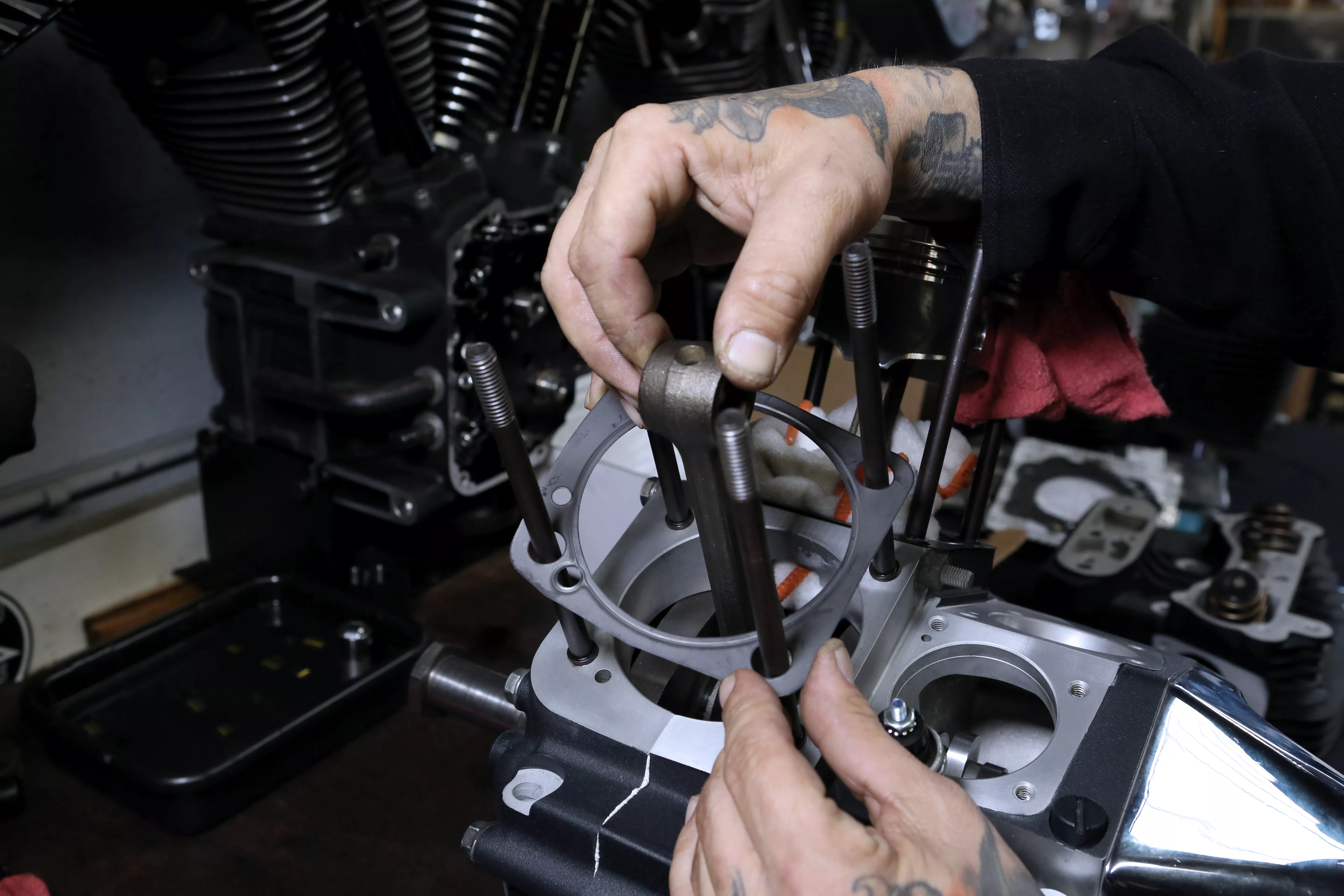
We simply placed the head gasket on the top of the head and over the dowel pins.
Words: Chip Kastelnik Photos: Mikey Van Senus
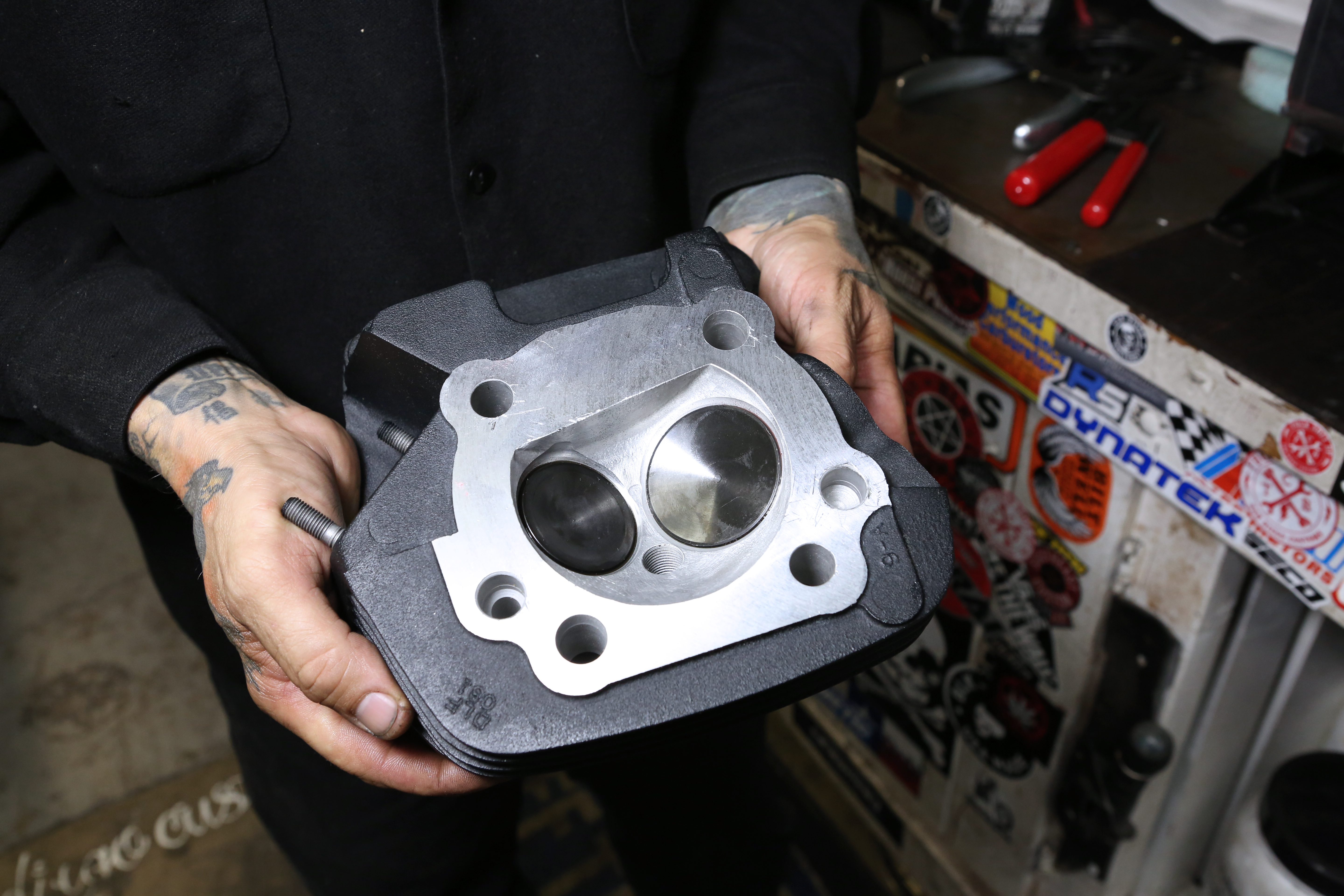
Verify the cylinder heads are clean are free of debris. These heads are Revolution Performance stage 4 heads, ported and worked.
Words: Chip Kastelnik Photos: Mikey Van Senus
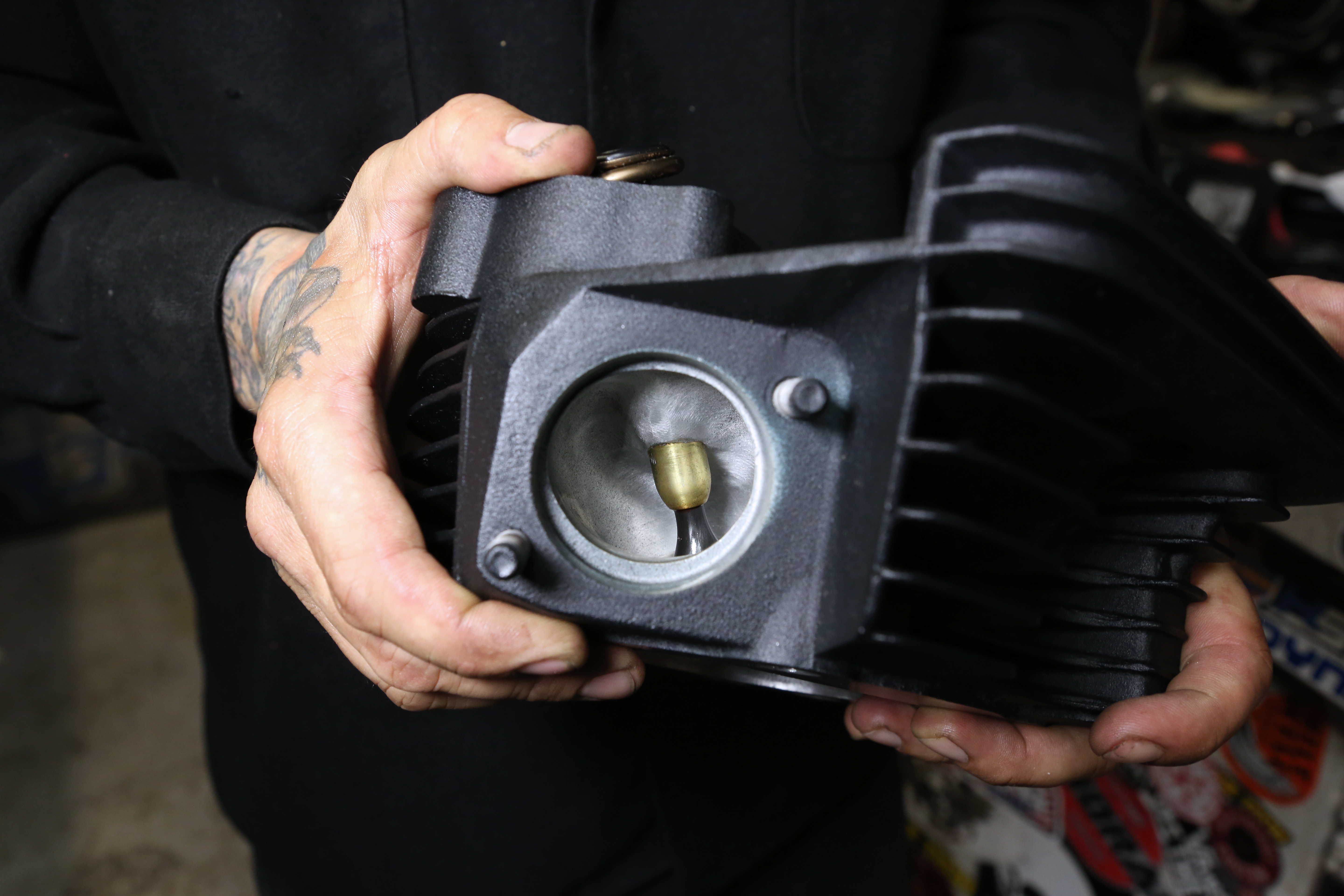
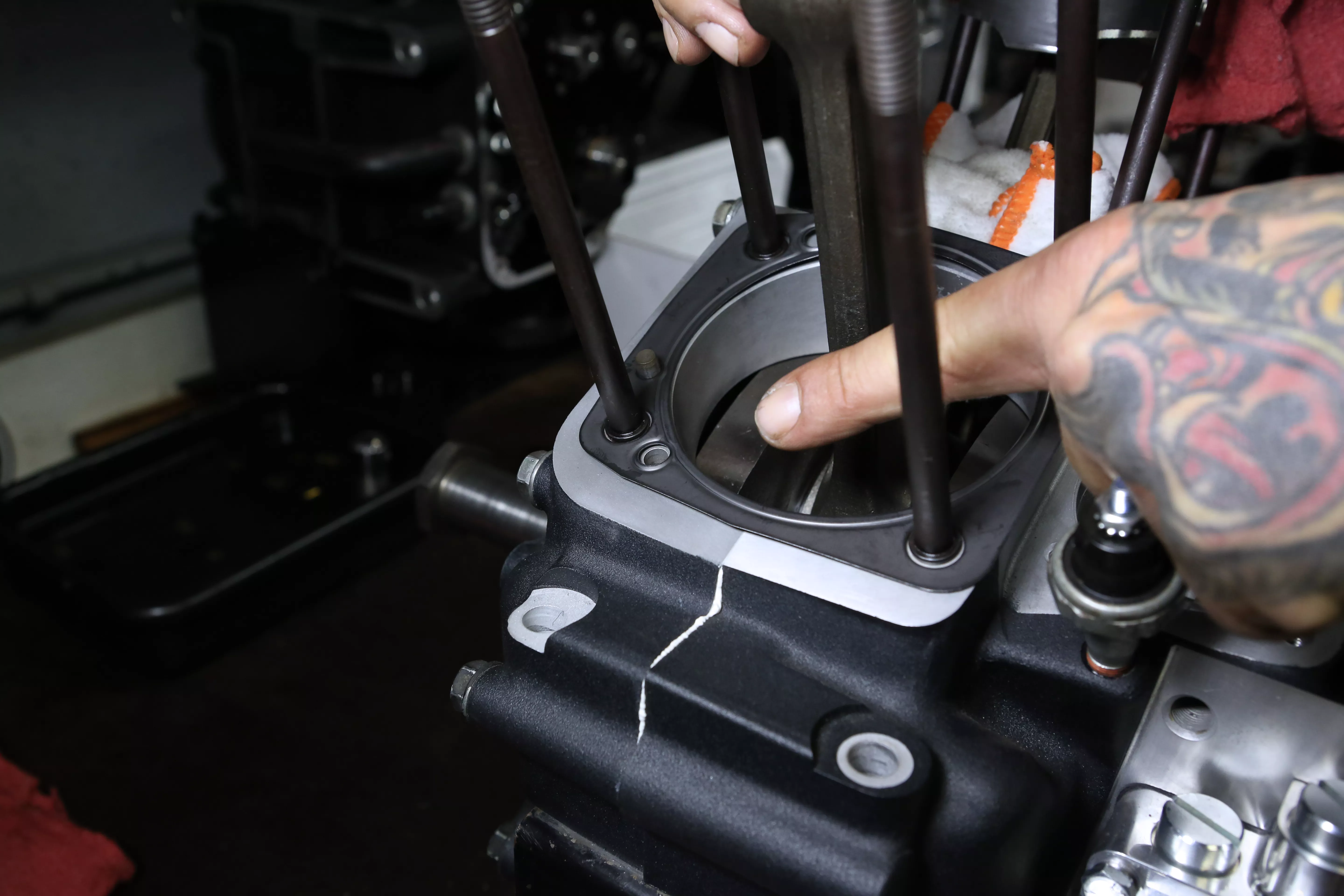
Here’s a peep into the exhaust chamber of the cylinder head.
Words: Chip Kastelnik Photos: Mikey Van Senus
We then installed the head over the head gasket and installed the head bolts. For this build we chose S&S stock length head bolts.
Words: Chip Kastelnik Photos: Mikey Van Senus
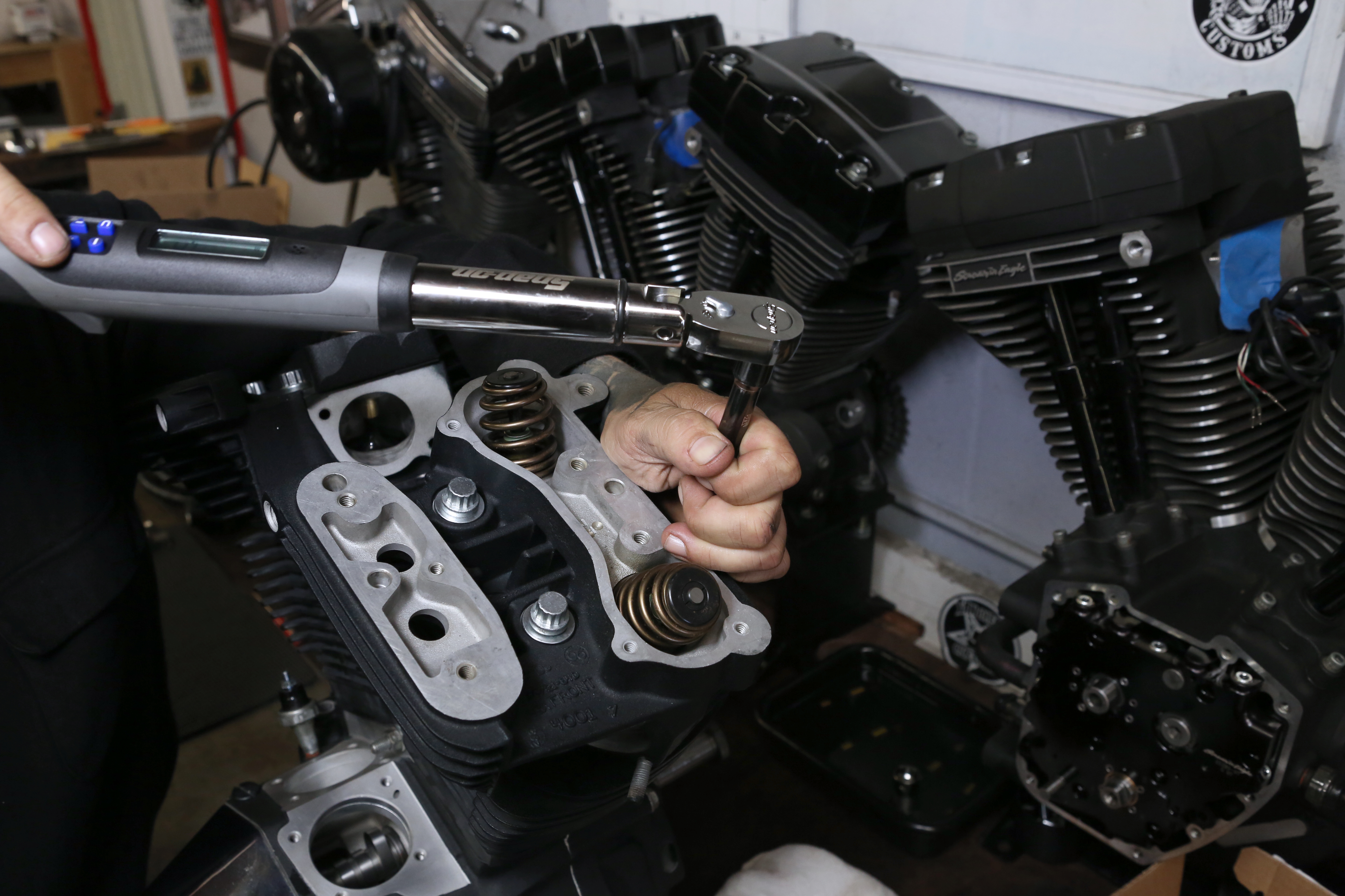
Next we torqued the head bolts as per the head gasket manufactures instructions.
Words: Chip Kastelnik Photos: Mikey Van Senus
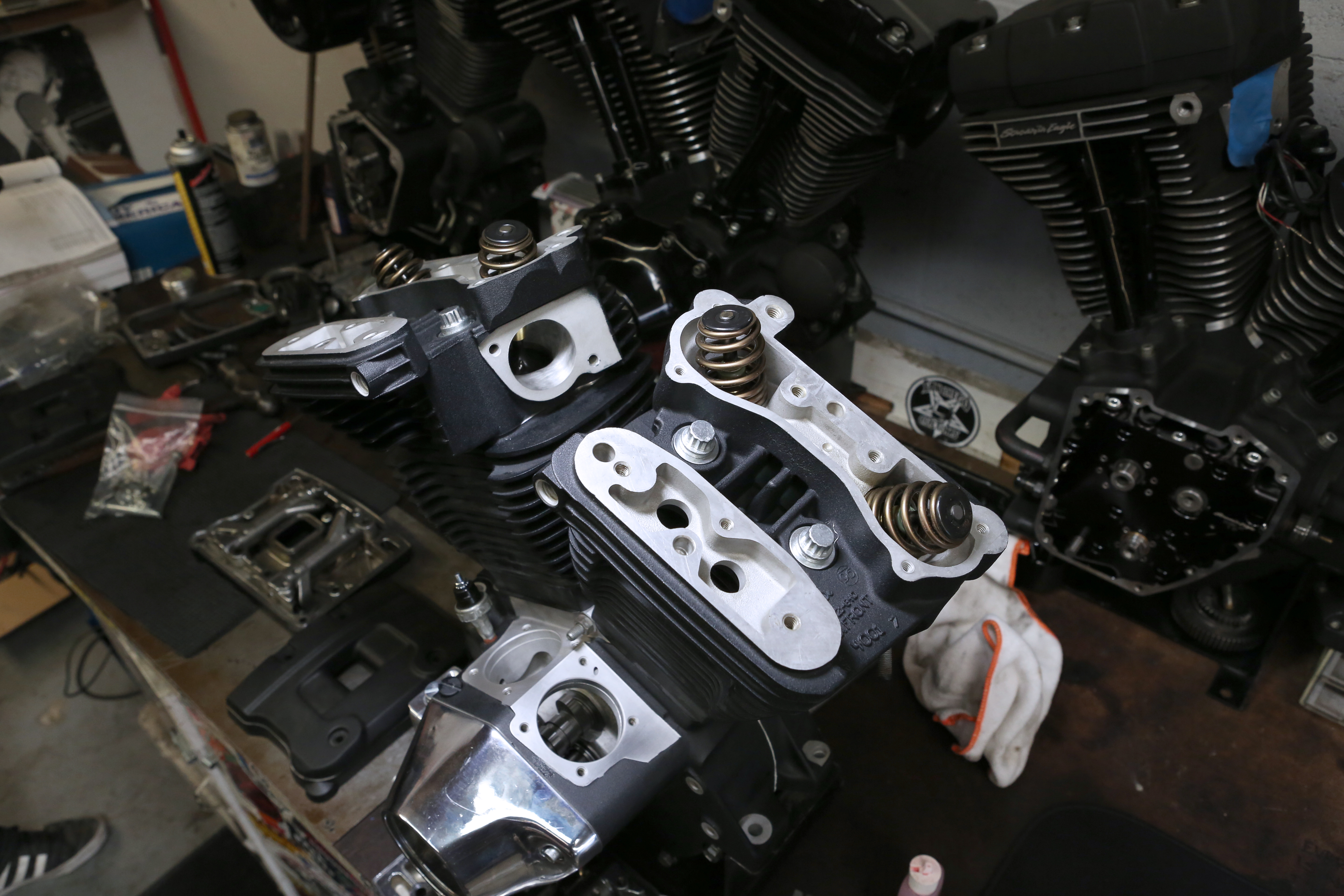
Pictured here is our motor with the cylinder heads installed.
Words: Chip Kastelnik Photos: Mikey Van Senus
RELATED | MORE TECH
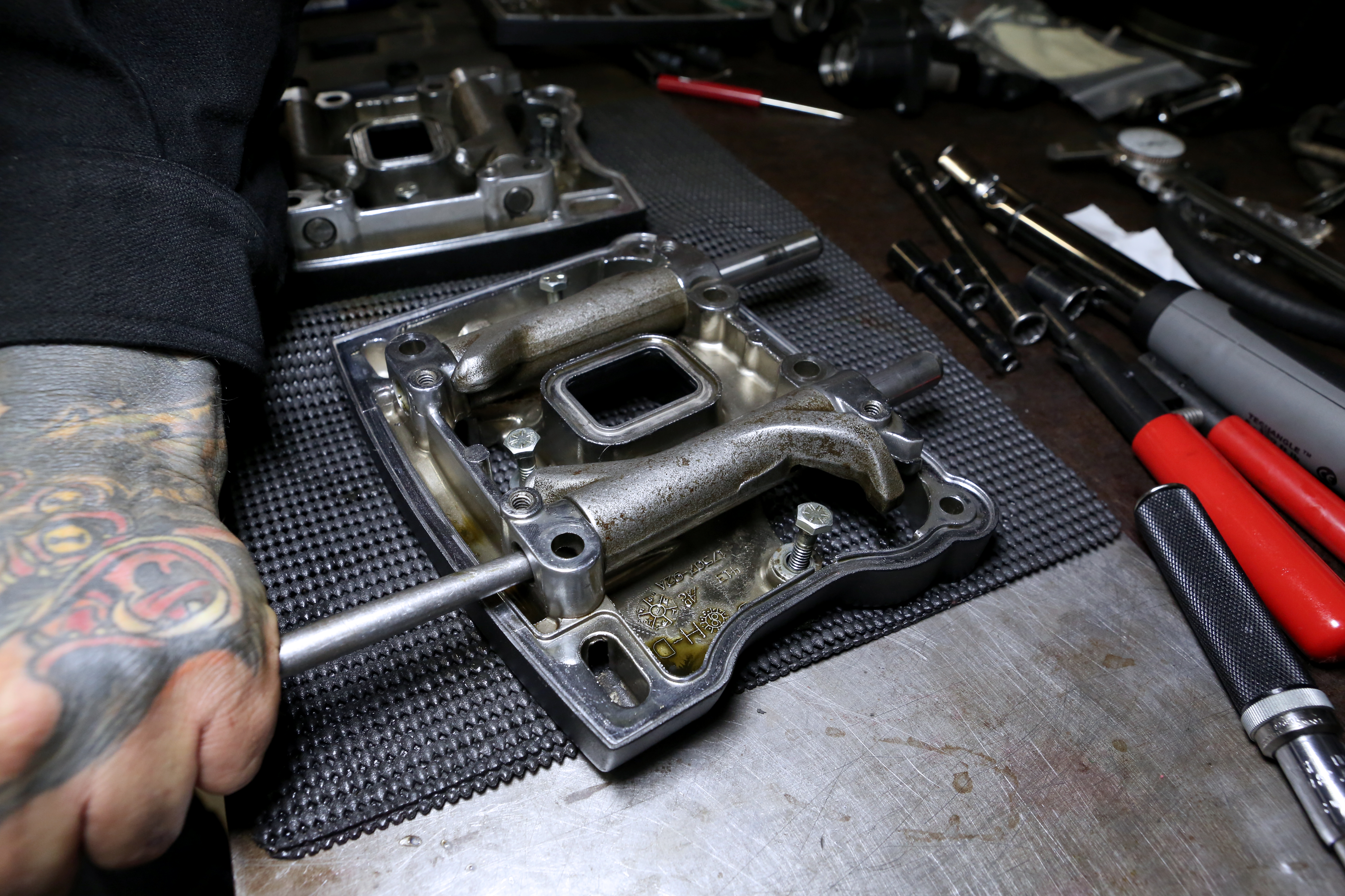
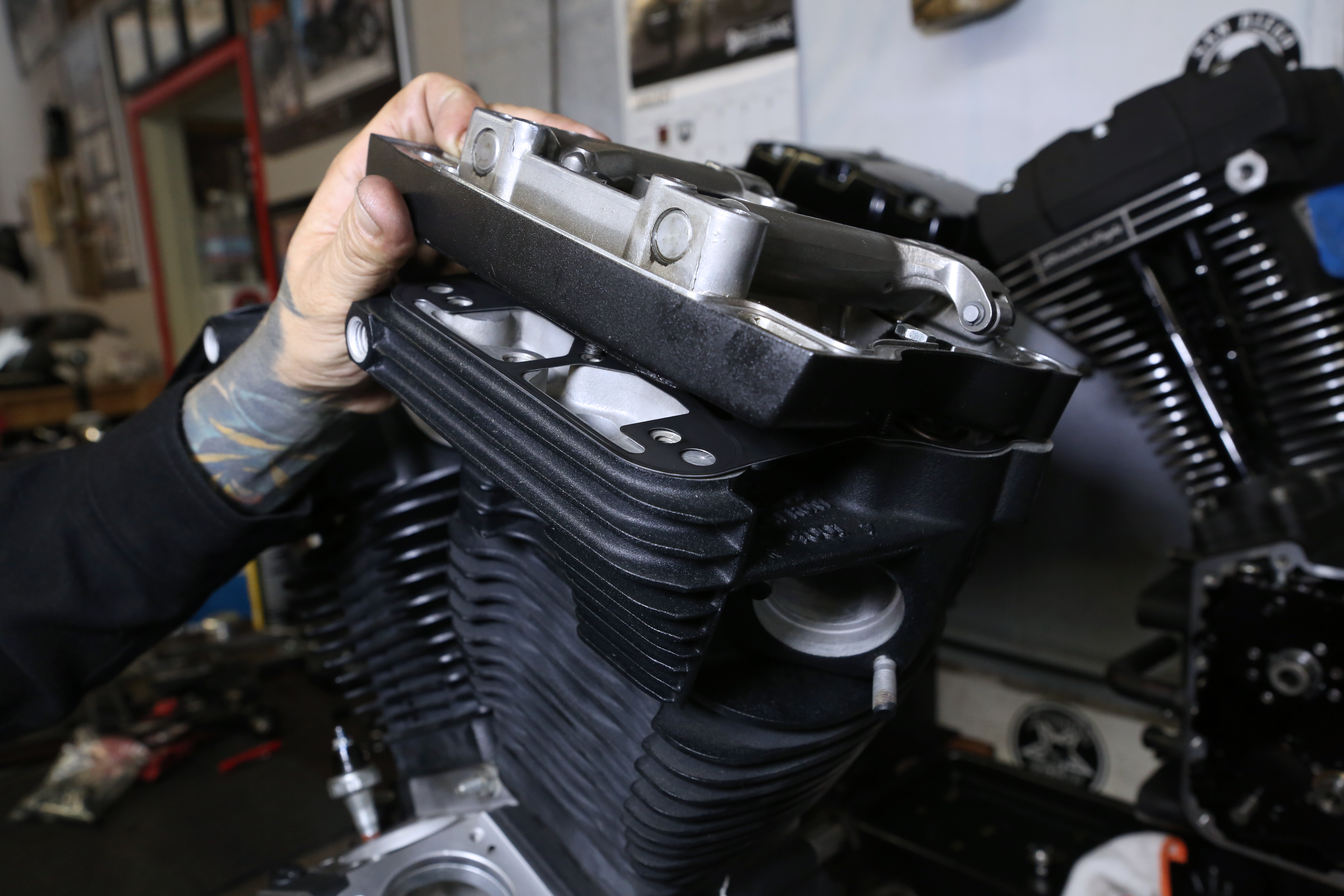
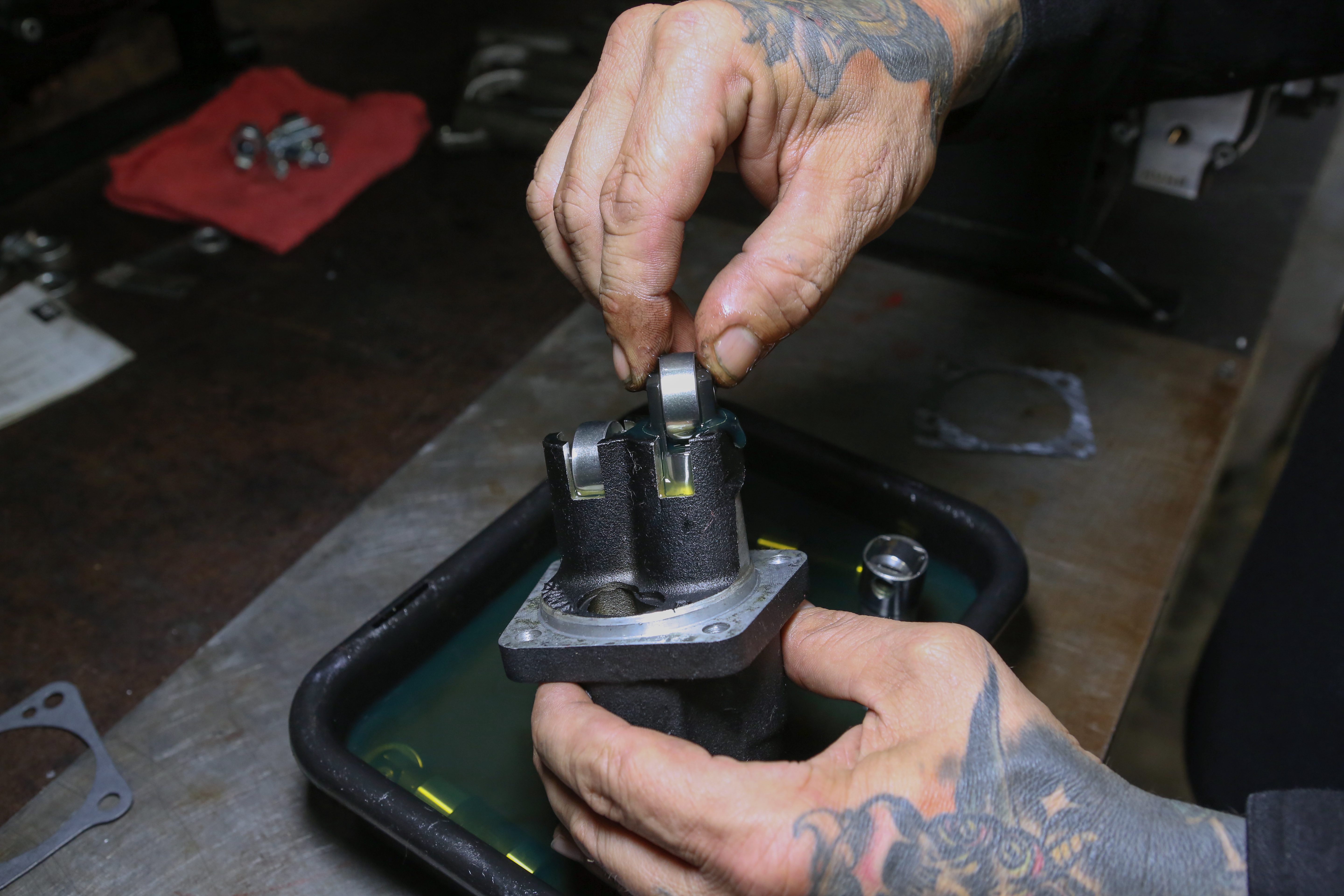
Next we disassembled the rocker boxes to measure the rocker bushings and replace the stock rockers to upgraded S&S roller rockers.
Words: Chip Kastelnik Photos: Mikey Van Senus
Knocking out the rocker arm shafts to measure and removing the rockers only takes a few minutes and can be the difference between a loud motor and a quiet one.
Words: Chip Kastelnik Photos: Mikey Van Senus
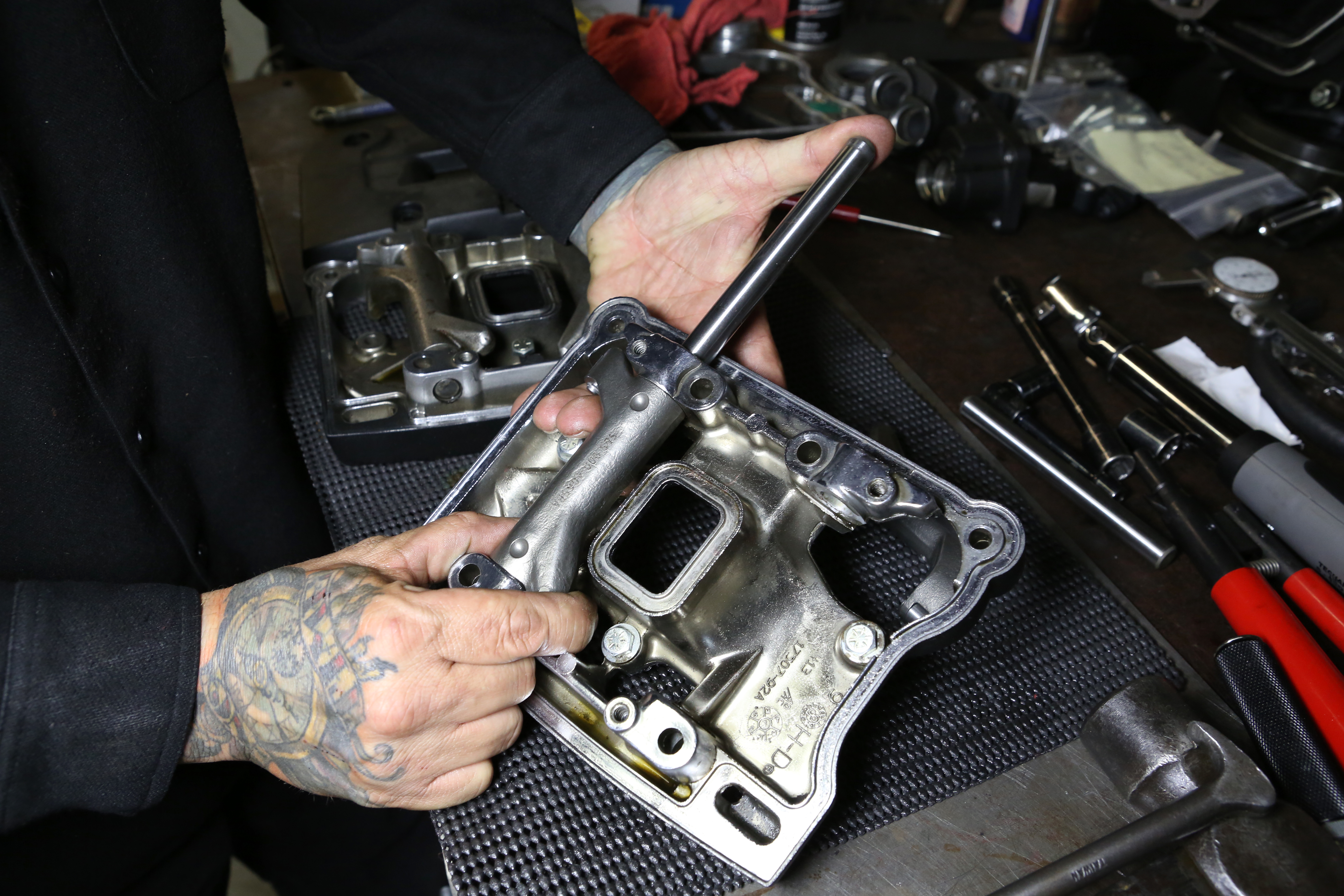
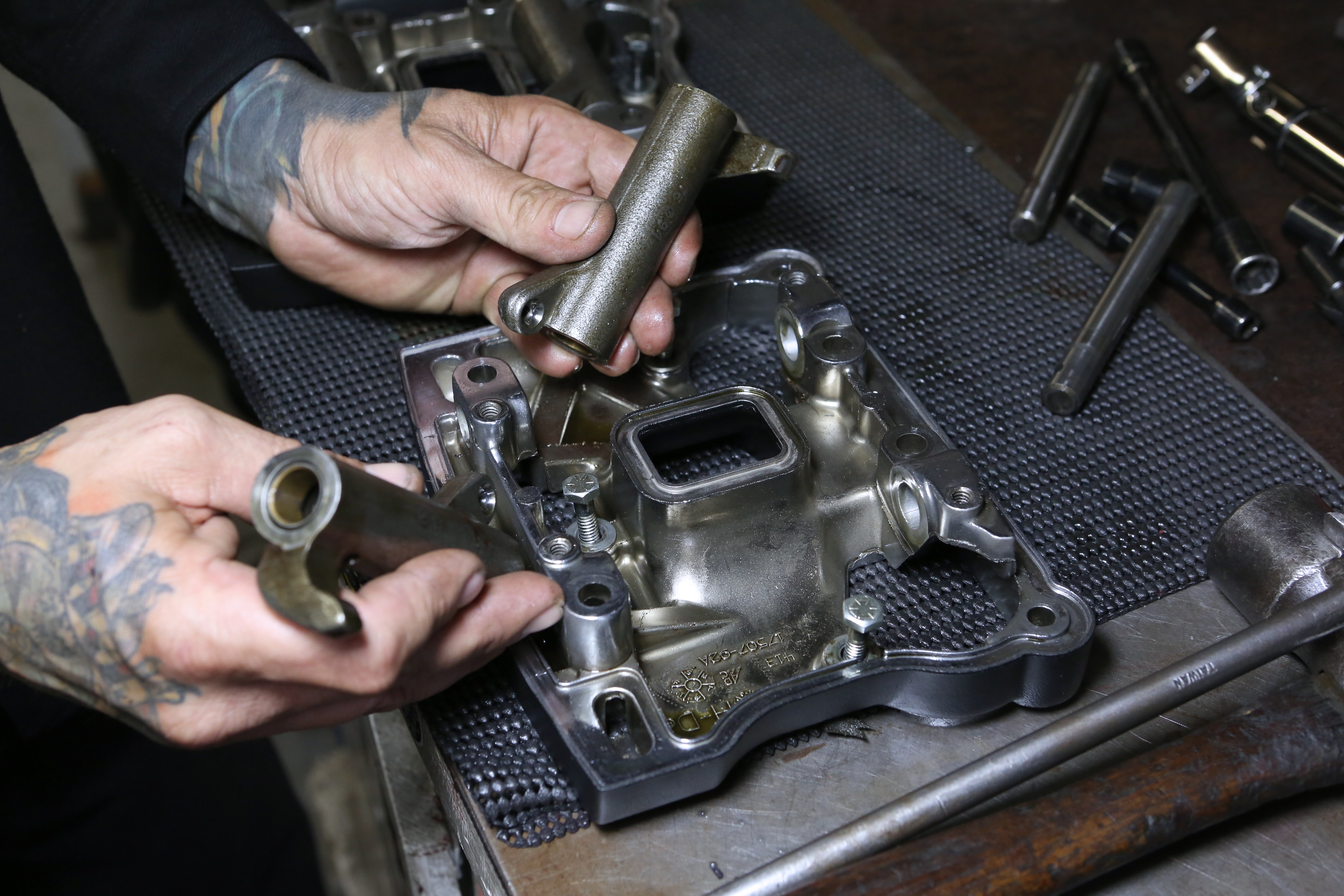
We installed new S&S roller rockers and shafts into the rocker support plate.
Words: Chip Kastelnik Photos: Mikey Van Senus
After assembling the rocker supports we installed the lower rocker gasket and the lower rockers onto the cylinder head.
Words: Chip Kastelnik Photos: Mikey Van Senus
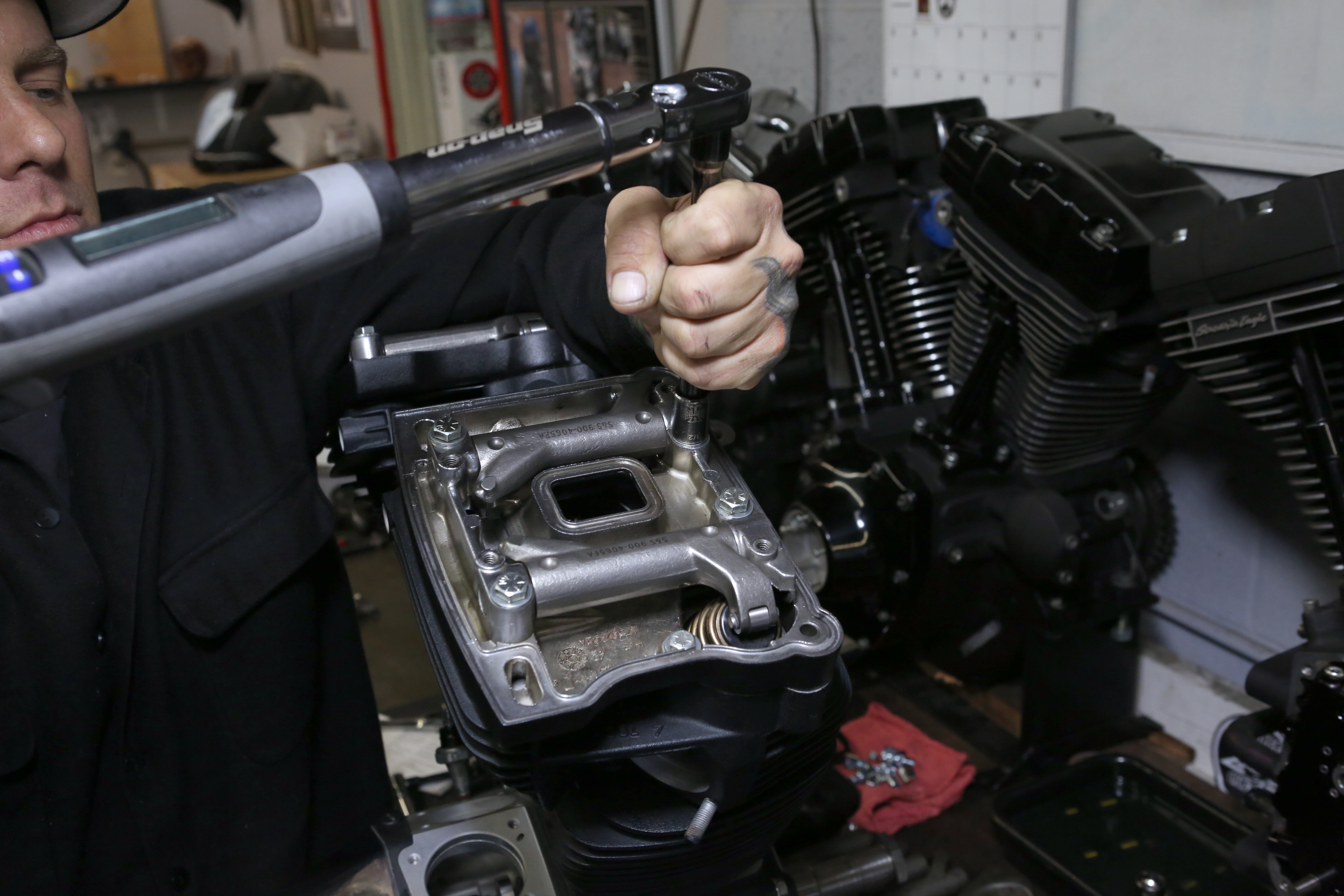
We torqued the lower rocker to factory specs.
Words: Chip Kastelnik Photos: Mikey Van Senus
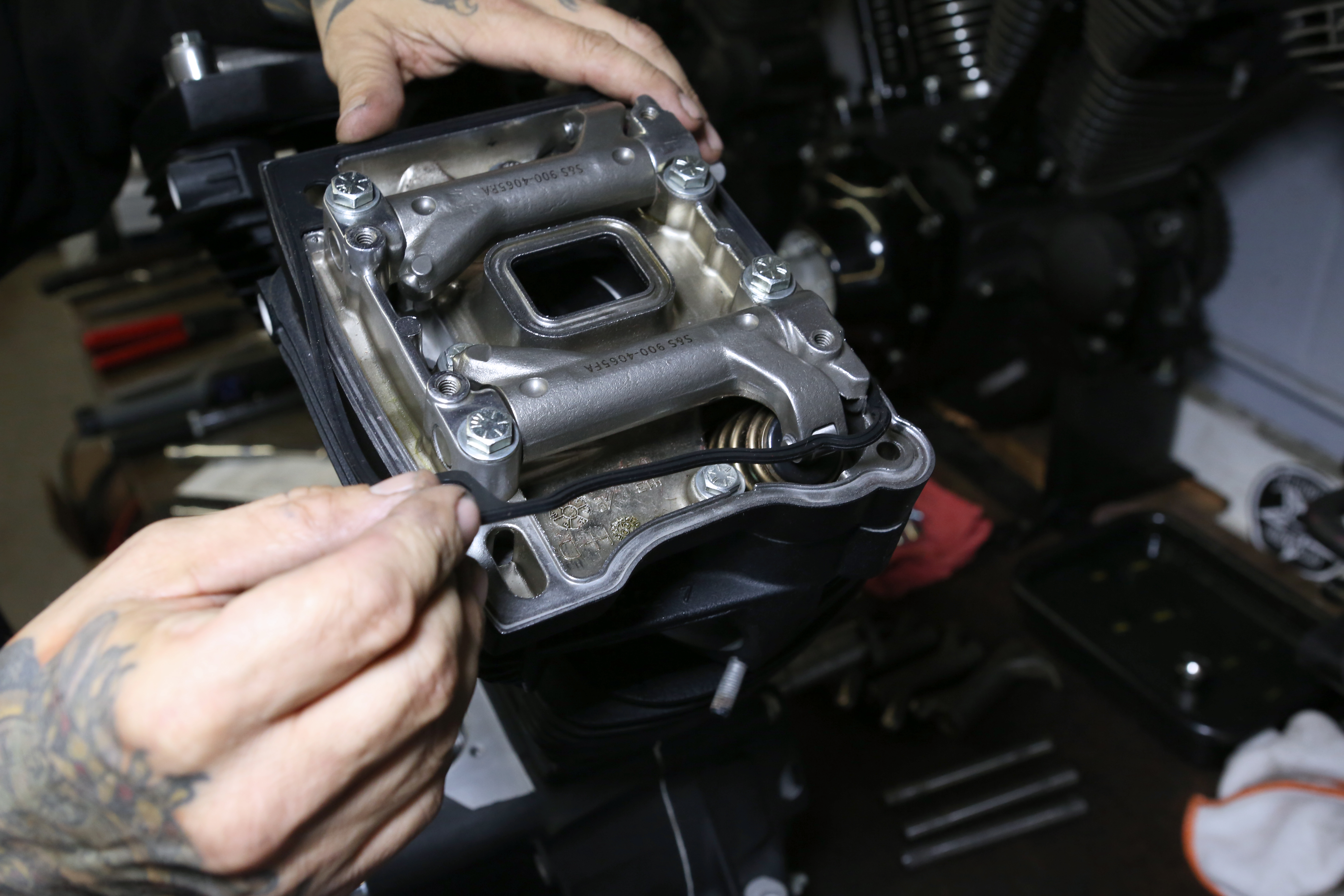
Then we installed the middle rocker gasket, making sure it fell into the groove.
Words: Chip Kastelnik Photos: Mikey Van Senus
Next we installed the middle rectangle gasket.
Words: Chip Kastelnik Photos: Mikey Van Senus
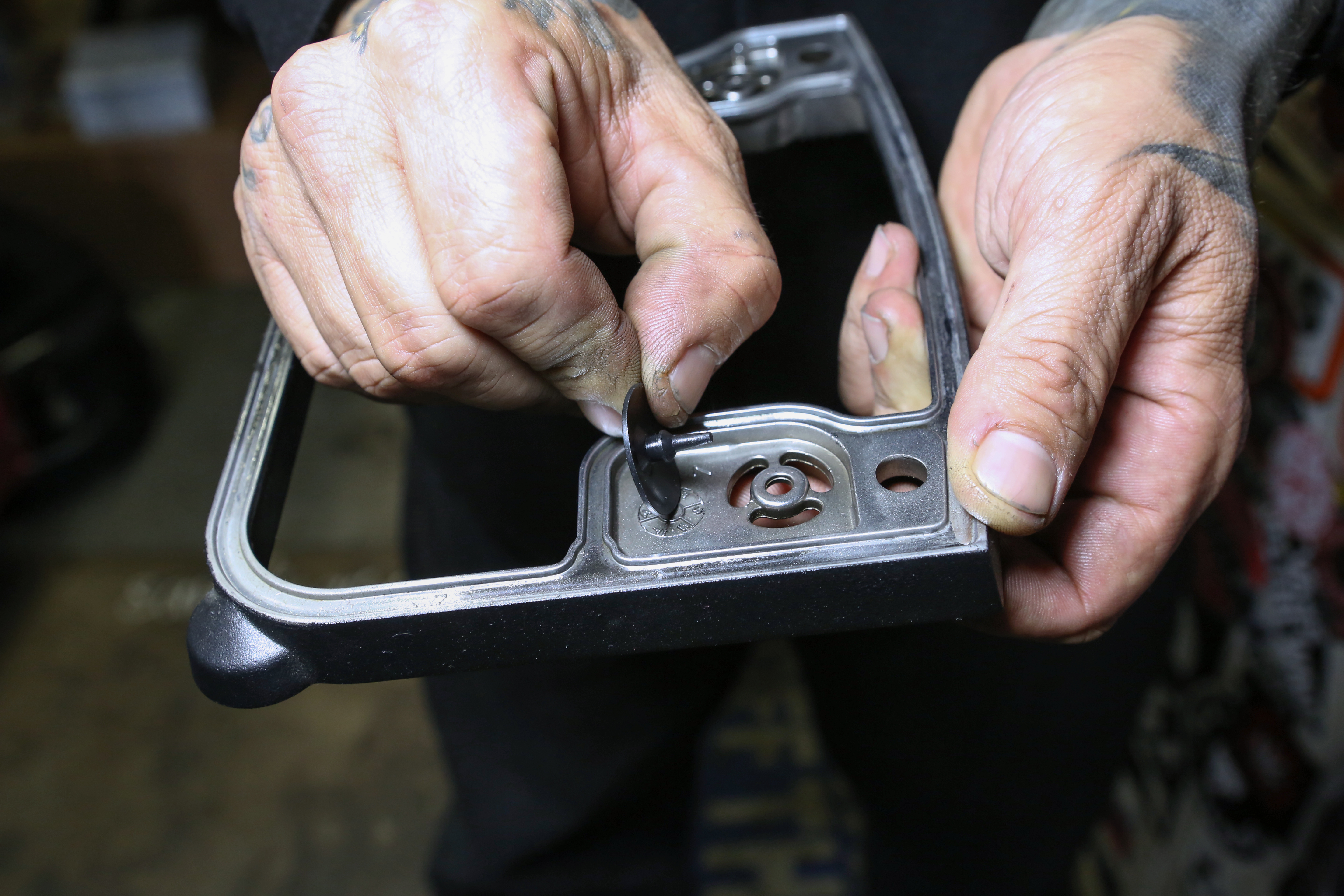
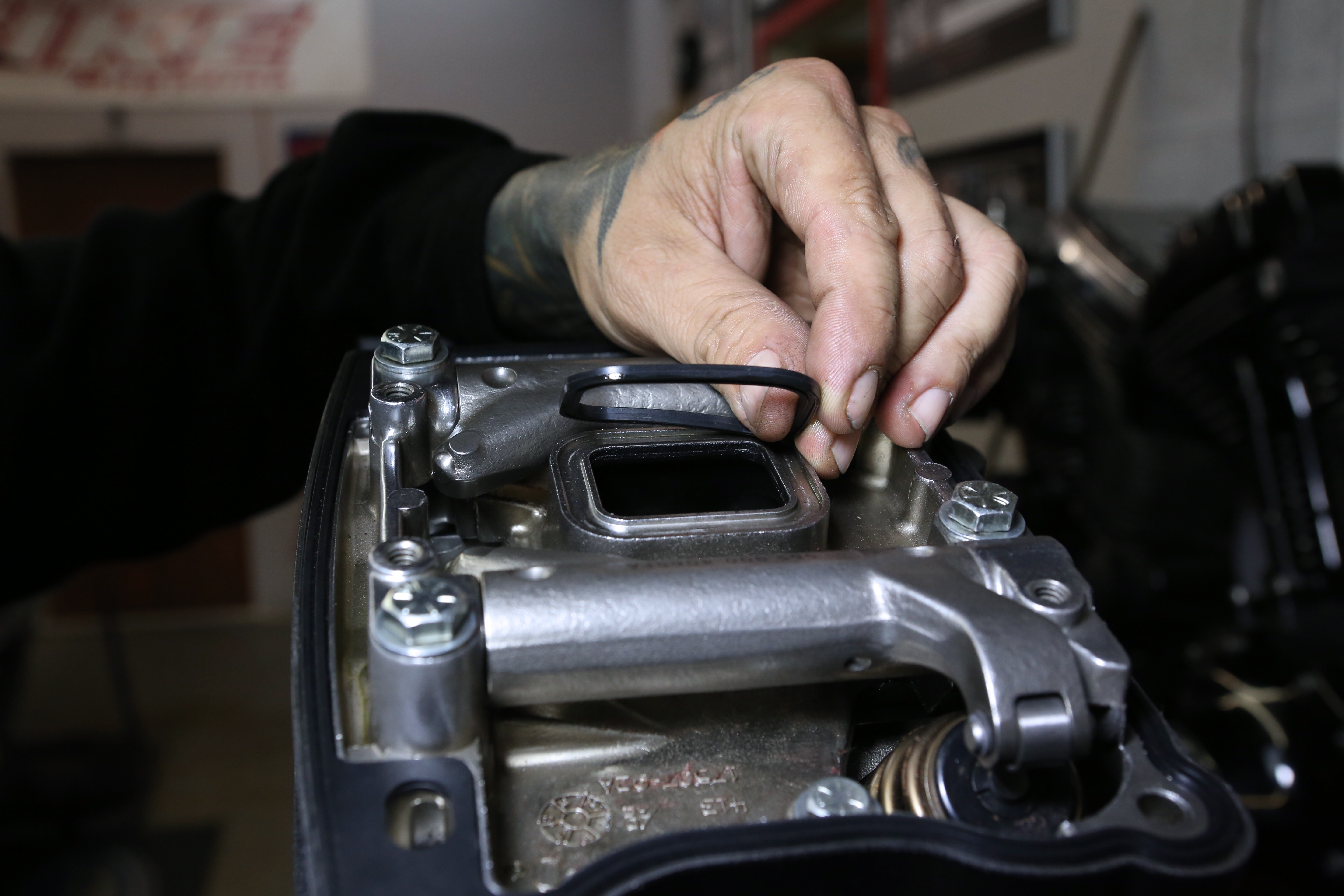
We installed a new umbrella valve breather gasket.
Words: Chip Kastelnik Photos: Mikey Van Senus
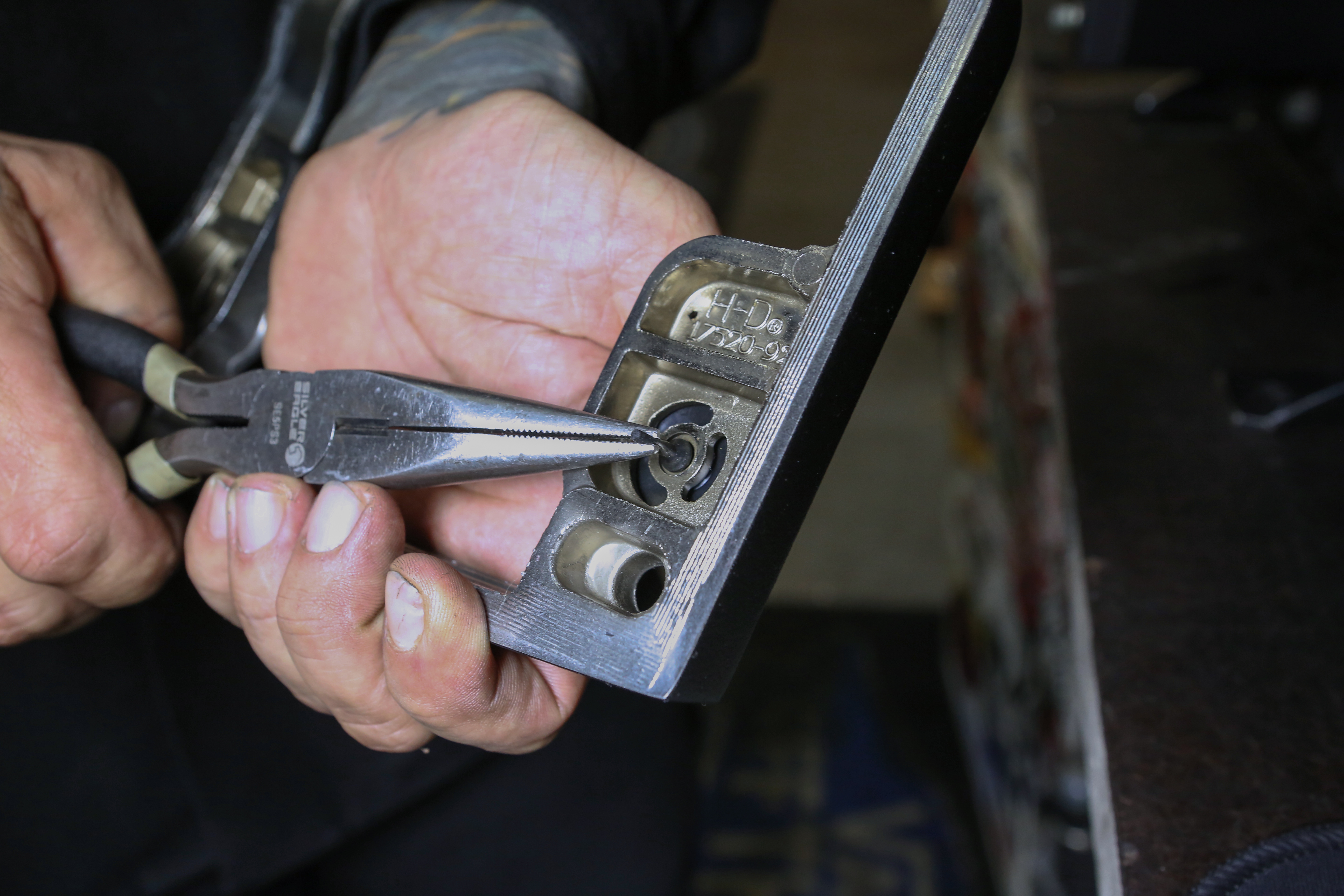
We used needle nose pliers to pull the tab through the rocker housing to be certain it can’t come loose.
Words: Chip Kastelnik Photos: Mikey Van Senus
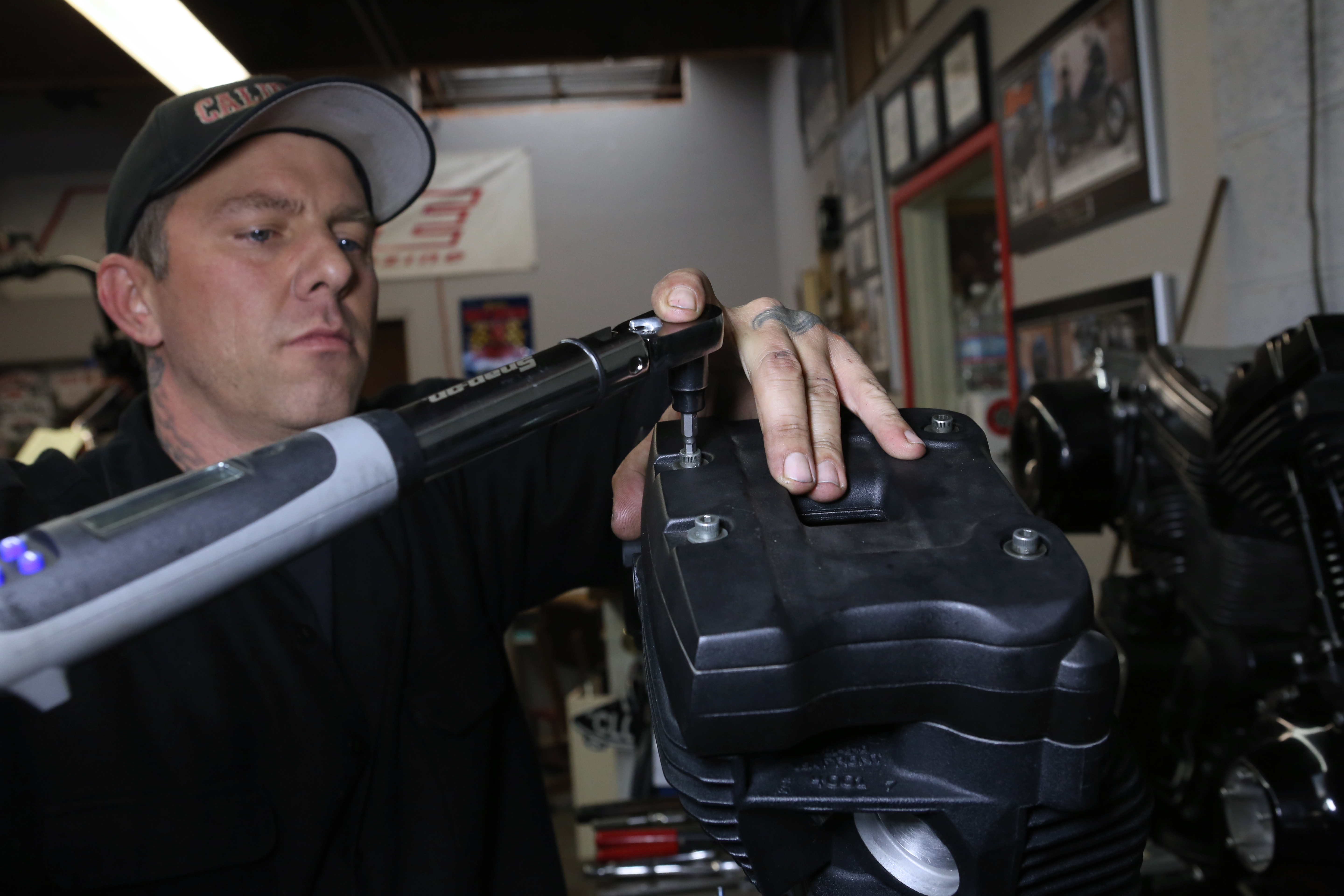
After installing the top rocker gasket and cover, we installed the 1/4-20 screws and torqued to factory specs.
Words: Chip Kastelnik Photos: Mikey Van Senus
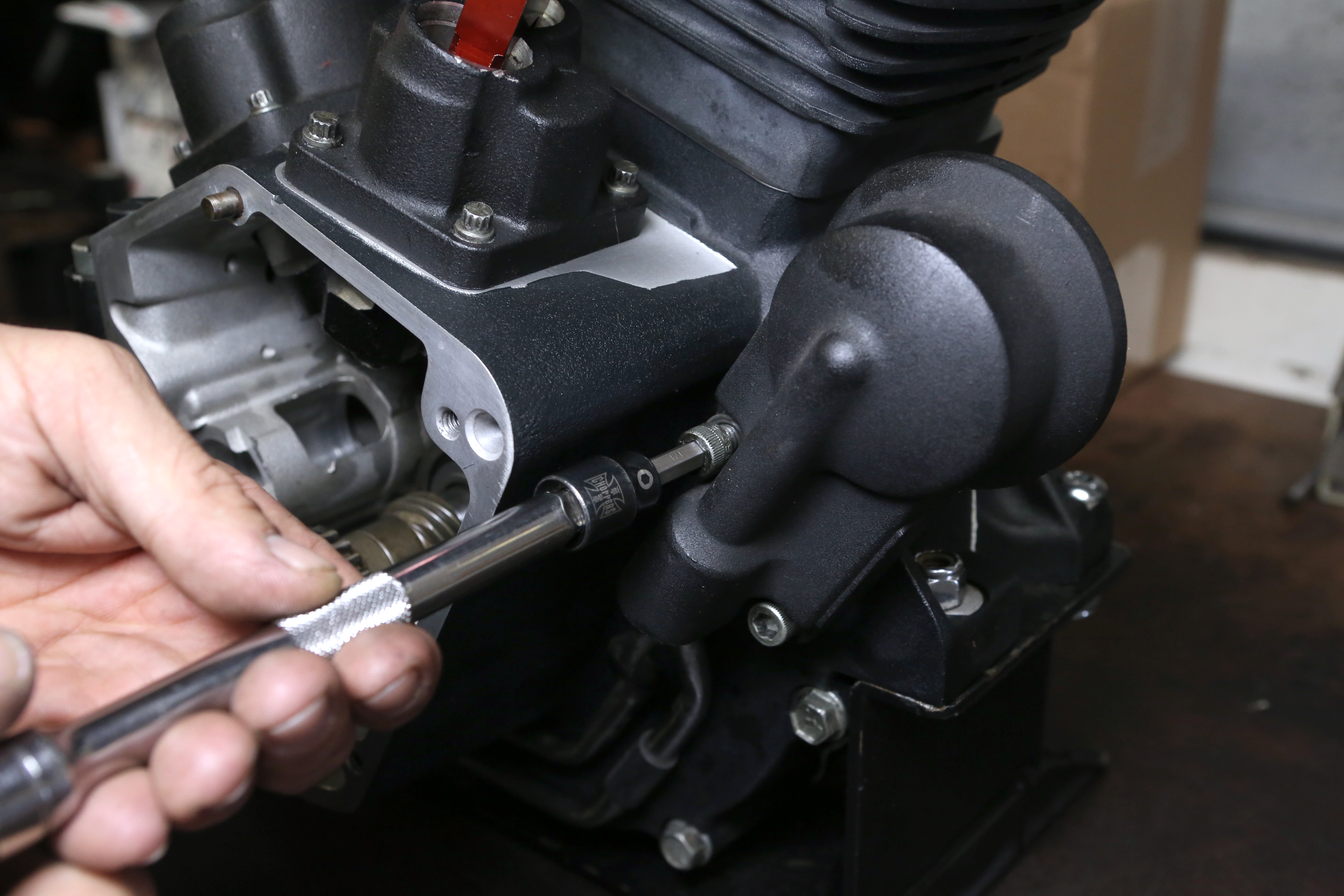
After pre-soaking the lifters, we installed them into the tappet blocks.
Words: Chip Kastelnik Photos: Mikey Van Senus
Then we installed the tappet blocks and gaskets into the appropriate cavity. Each block is marked front and rear.
Words: Chip Kastelnik Photos: Mikey Van Senus
Lifters installed.
Words: Chip Kastelnik Photos: Mikey Van Senus
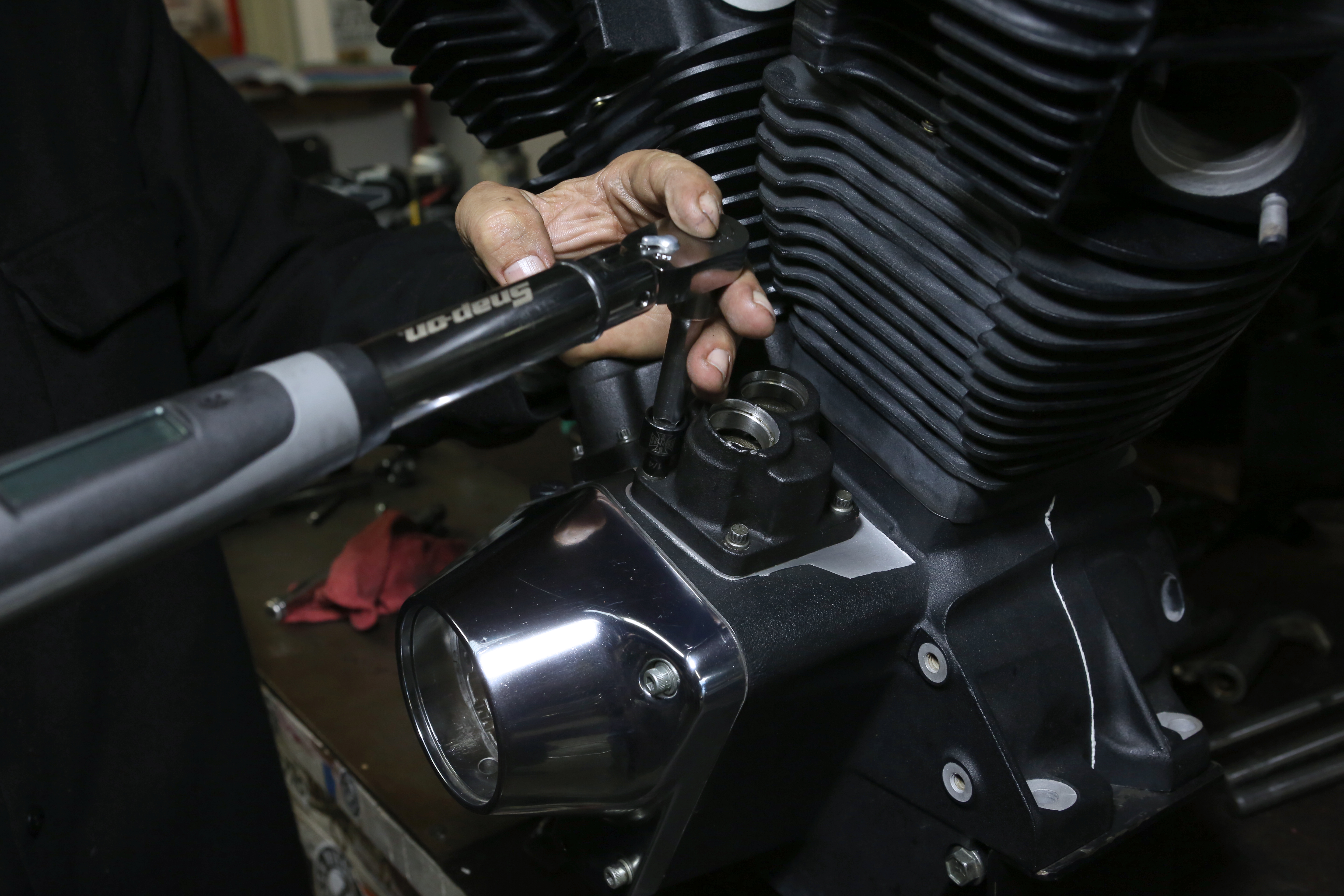
We torqued the tappet black to 90–120 inch-pounds as per the factory service manual.
Words: Chip Kastelnik Photos: Mikey Van Senus
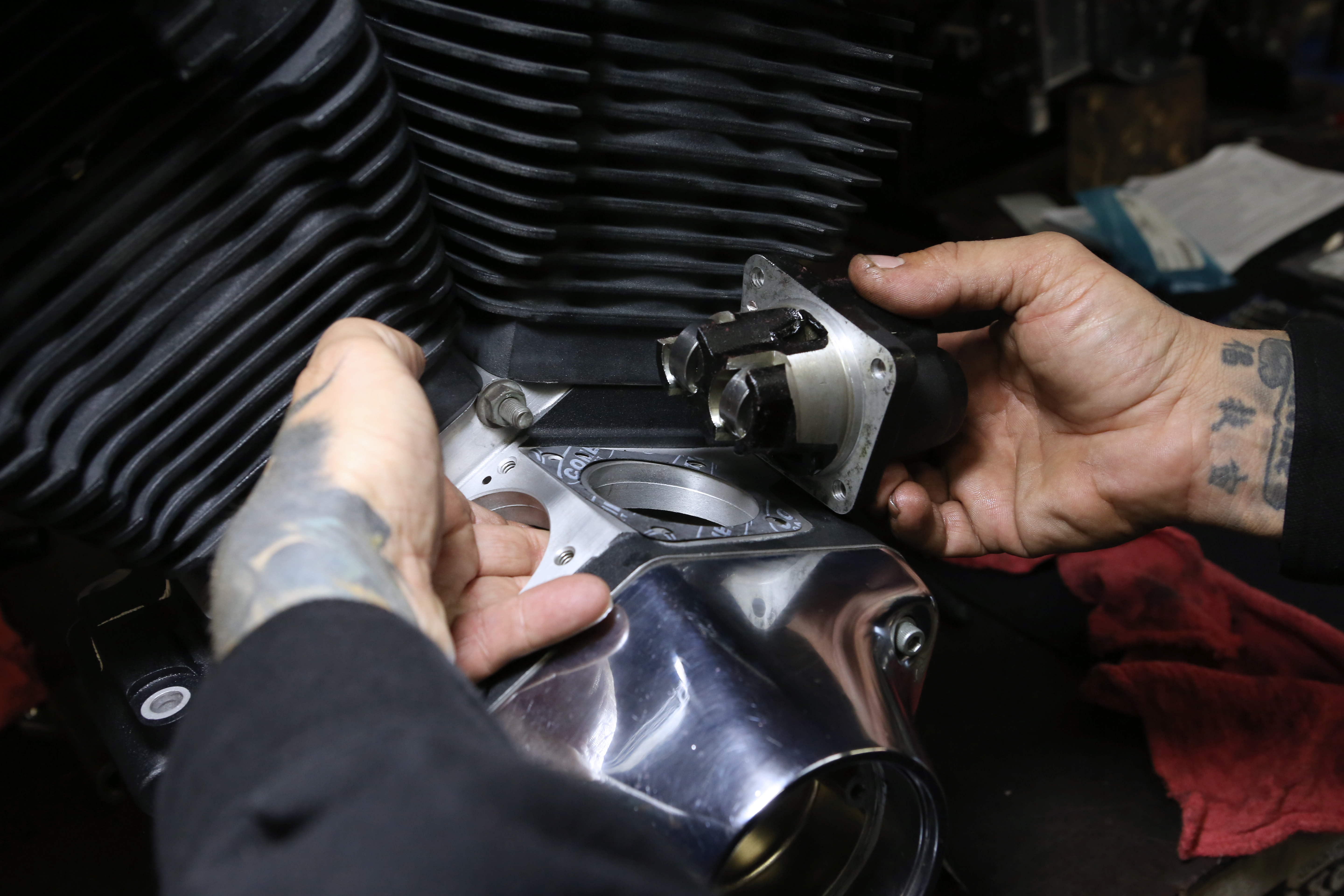
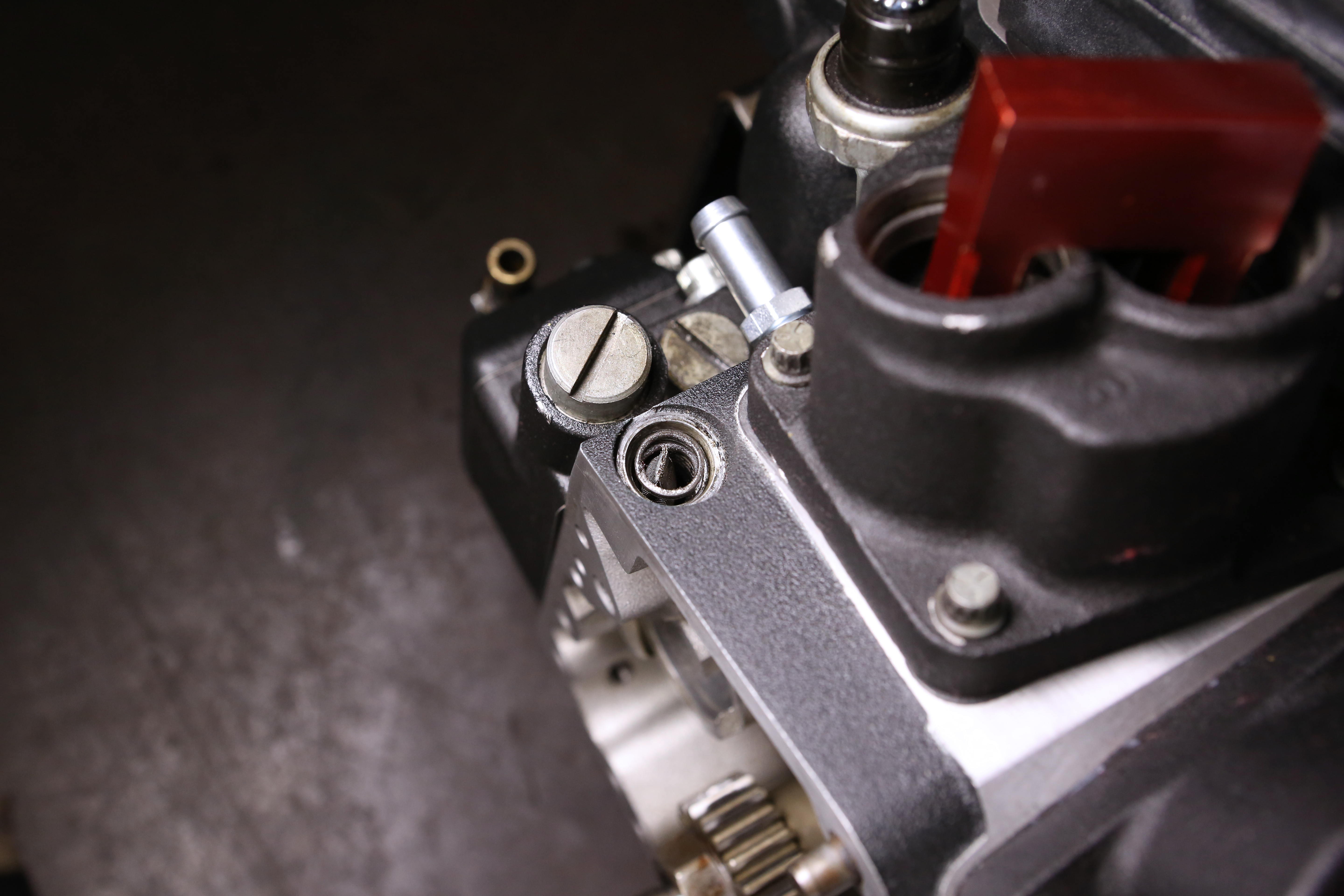
Next we installed the oil filter mount and tightened the town bolts to factory specs.
Words: Chip Kastelnik Photos: Mikey Van Senus
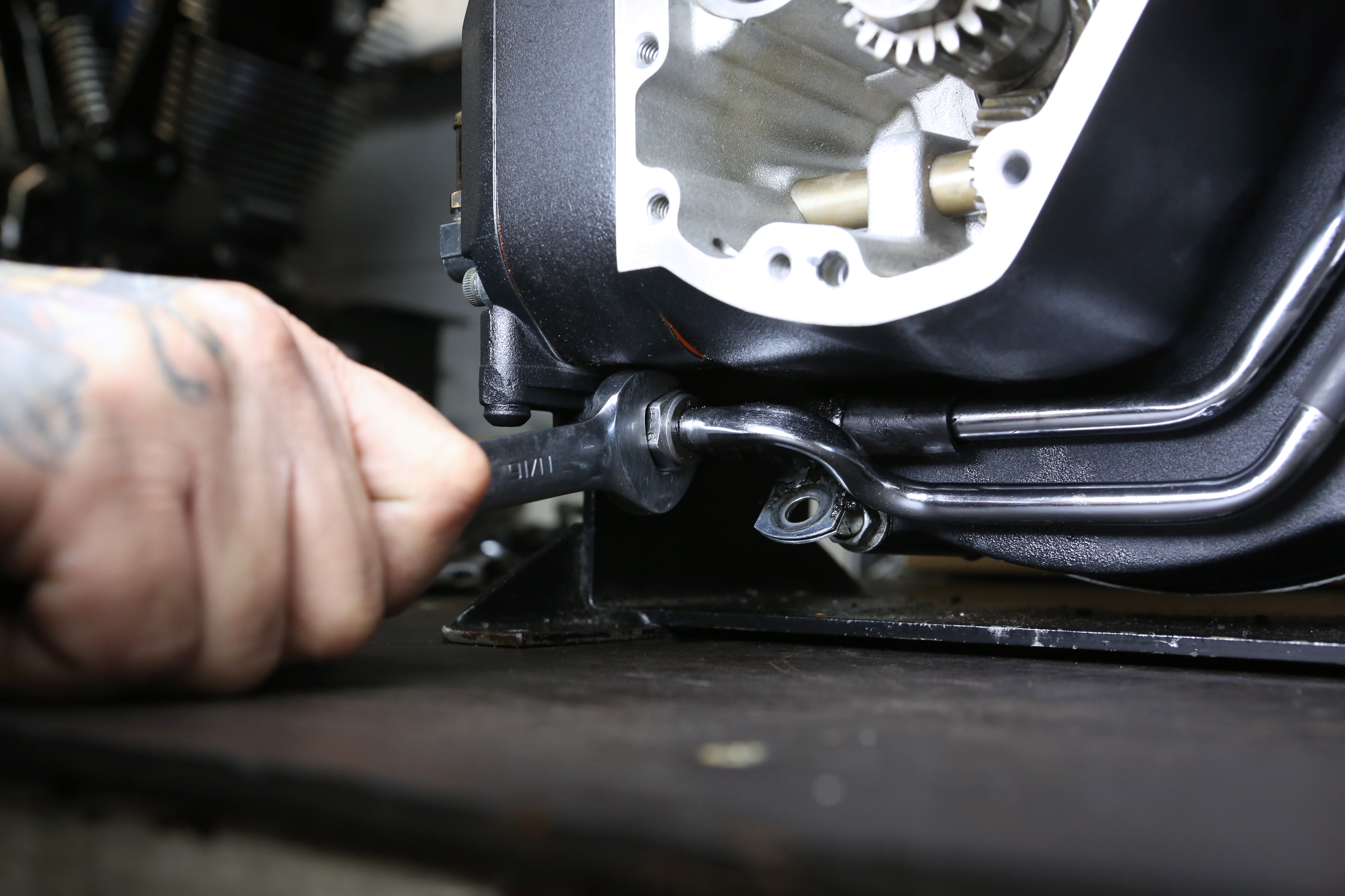
Next we installed the OEM oil lines and their gaskets. Be sure to tighten all fittings to factory specs.
Words: Chip Kastelnik Photos: Mikey Van Senus
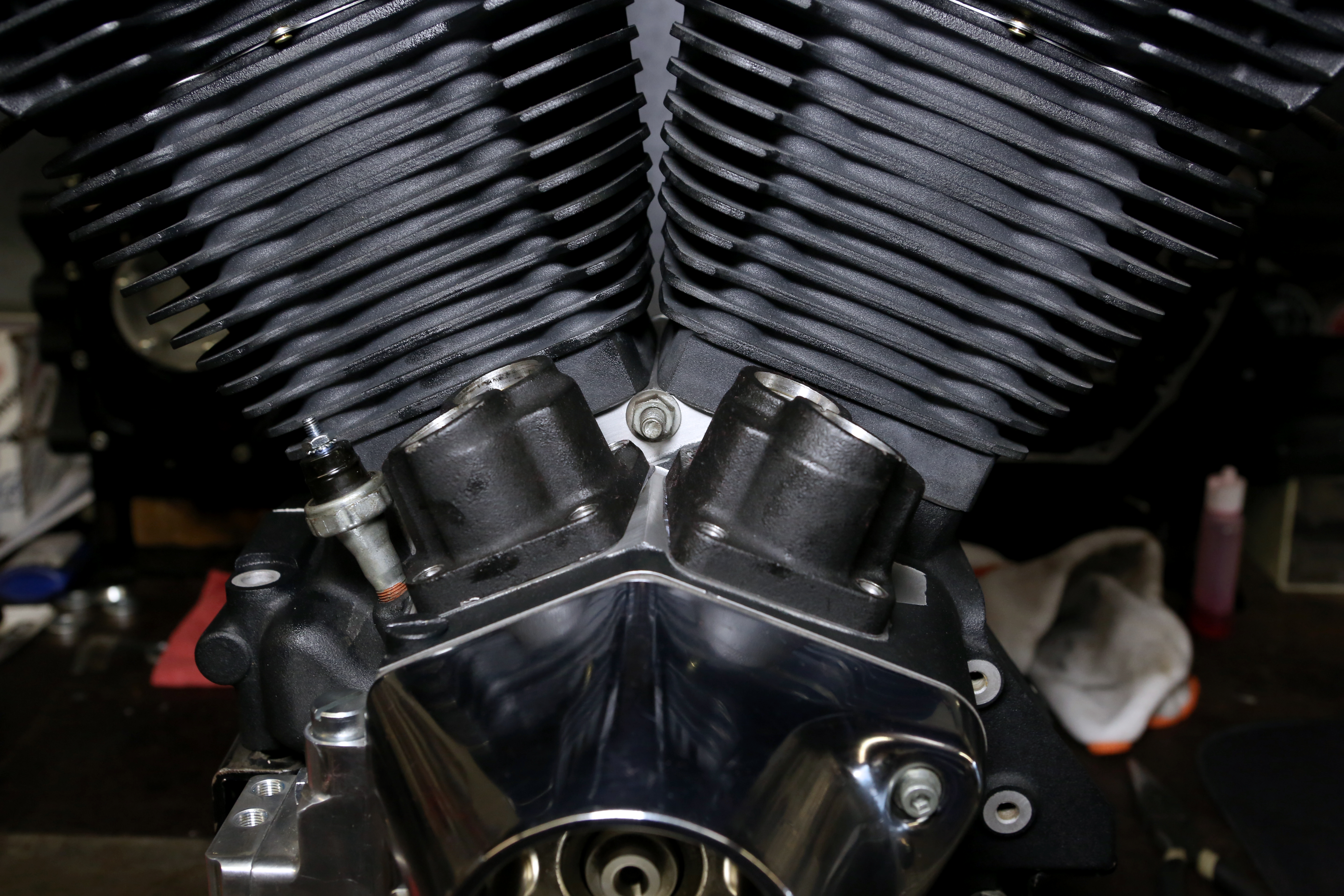
Verify your oil system components are installed and debris-free.
Words: Chip Kastelnik Photos: Mikey Van Senus
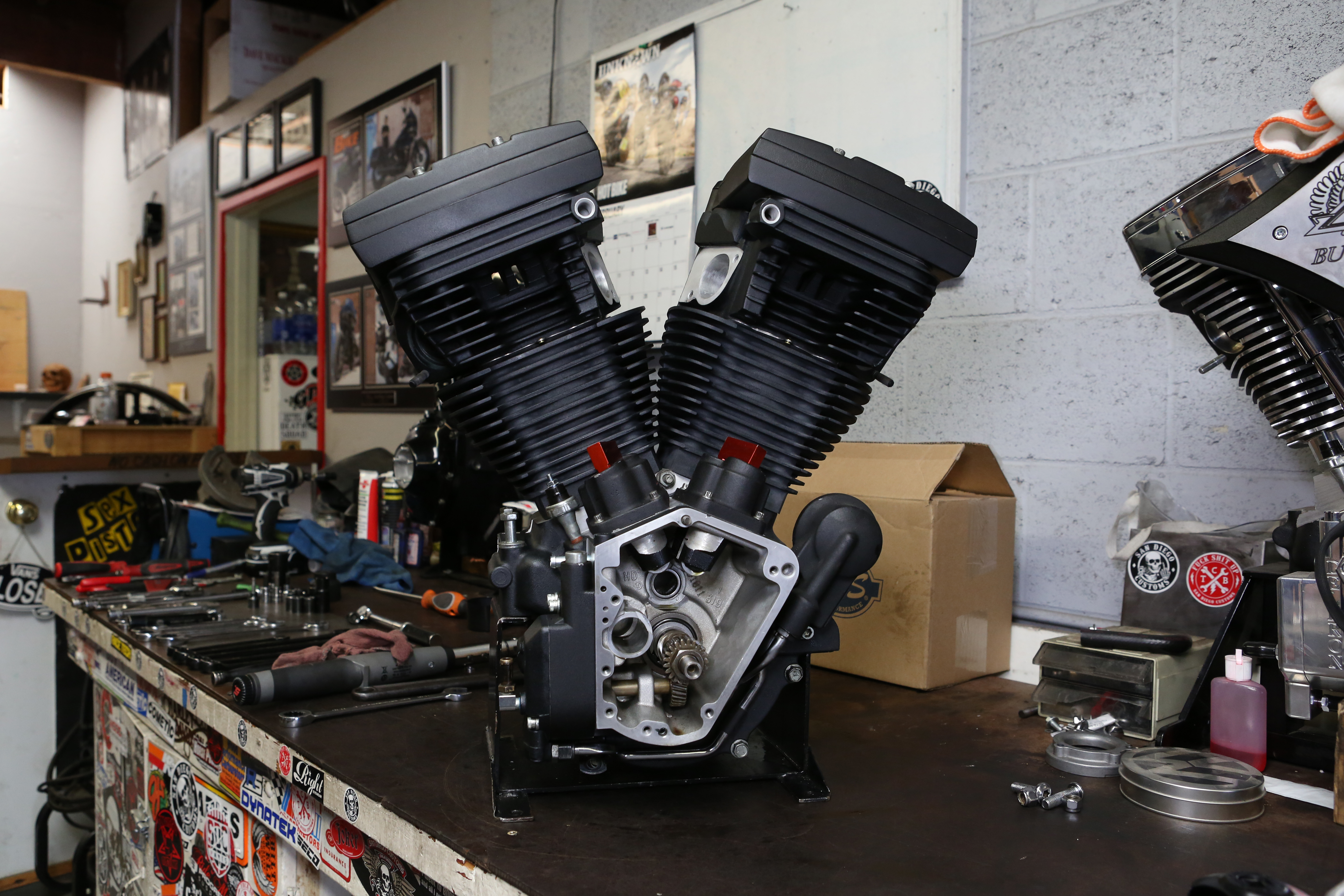
Pictured here is our rebuilt, refreshed 1997 H-D Evolution motor that will provide ample power and a pleasing ride. Check out revperf.com for any additional details.
Words: Chip Kastelnik Photos: Mikey Van Senus
Sources
Get more tech for your buck when you subscribe to Hot Bike at our discounted rate.


